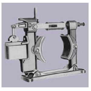
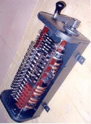
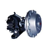
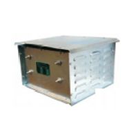
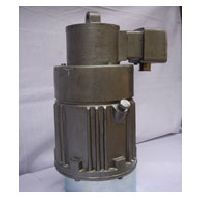
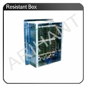
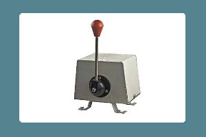
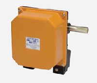
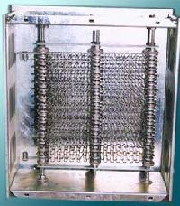
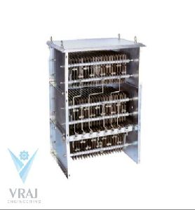
A guide to the application and selection of sterling shoe type brakes It is often essential for safety, control or convenience that a machine driven by an electrical motor should be stopped, slowed or held stationary against gravity or other forces. In most cases, because of the need to apply the brake automatically in the case of power failure or other interruption, these brakes are normally of the `FAIL-SAFE’ type. Fail-Safe type brakes are usually applied by means of springs or in some cases by dead weights. The brake release is in most cases electrical and when power is applied the electrical actuator releases the brake and the motor on which the brake is fitted is free to run at it’s normal rated speed. The simplest and most effective control is achieved by connecting the brake and motor in parallel so that the brake is released while the motor is running and applies as soon as power to the motor is cut off. In practice the brake is connected across 2 or 3 of the supply terminals of the motor which the brake is controlling, dependent on the brake release actuator being used. Satisfactory operation of the braking system requires correct selection of the brake type and size, and this selection is dependent on the application, duty cycle and some characteristics of the drive and it’s components. STERLING shoe type brakes usually operate either on a flexible brake drum coupling connecting the motor to the gearbox or other drive component or on a brake drum fitted on the non-drive end of the motor or the input shaft extension of the gearbox if available. The brake shoes, lined with friction material, clamp the drum under the influence of pressure from the compression springs and release evenly when the electro-magnetic solenoid, thrustor, pneumatic cylinder or other actuator is energized. STERLING Brakes are used on almost any type of motor driven equipment where controlled stopping, slowing or holding of the drive motor is desired. Some of the common machines on which brakes are used are : Roll Former’s, Calendars, Conveyors, Extractors, Centrifuges, Screw Feeders, Granulates, Cranes and Hoists, Coil Winders, Rubber Mixing Mills, Baling Presses, Large Machine Tools, Steel Rolling Mill Stands, Coolers, Uncool and several other types of industrial drives. In various applications the exact requirements are dependent on the use. Some users may require to stop the motor by plugging and holding the motor stationary against a load, while other requirements may call for the use of a brake for both the same functions. Some requirements call for the use of brakes for positioning of driven machinery while others Require brakes for safety or for preventing damage to driven machinery in the event of a power failure or other interruption. STERLING can provide brakes for almost any requirement. We manufacture a variety of brakes of different type and while all brakes would stop a given motor, each type has different characteristics, specifications and prices and actual selection would depend on the user’s particular requirements. Our range of brakes has the following categories: Single Phase AC Electro-Magnetic Brakes [PRODUCT CODE 10] Hydraulic and Mechanical Manual Brakes [PRODUCT CODE 11] Three Phase AC Electro-Magnetic Brakes [PRODUCT CODE 13] Electro – Hydraulic Thrustor Brakes [PRODUCT CODE 14] Thrustor Operated Creep Speed Brakes [PRODUCT CODE 15] D. C. Electro-Magnetic Brakes [PRODUCT CODE 16 & 17] Pneumatic (Or Hydraulic) Powered Brakes [PRODUCT CODE 19] STERLING SINGLE PHASE ELECTRO-MAGNETIC BRAKES [PRODUCT CODE 10] Features very fast application and release, and suitable for unto 120 or 240 operations per hour depending on the coil rating. Higher operating rates are permissible for short time intermittent operation but mechanical life is limited due to constant impact of the magnet lamination. Standard brakes are supplied with coils wound to accept a 415 VAC, 50 Hz. 2 Phase supply allowing the brake to be connected across two of the three terminals of the motor it is connected to. Other voltages are available as Ideal for low cost, light duty applications. Requires regular maintenance and periodical replacement of worn parts and coils. STERLING HYDRAULIC AND MECHANICAL MANUAL BRAKE [PRODUCT CODE 11] These manual brakes are used to supplement the electro-mechanical brakes mainly to provide operator controlled braking in addition to the automatic braking action and allow the operator extra control on slow motor speeds to cater for variations in load. These brakes are normally reverse acting, non-fail-safe types where the brakes are spring released and manually applied similar to the braking action of automobile. Two systems are available with the control being hydraulic in one case and purely mechanical in the other. The hydraulic system involves a foot pedal operated master cylinder on the operator side and a slave cylinder in the brake inter-connected with tubing while the mechanical system involves mechanical linkages such as wire ropes etc. between the operator and the brake. The former allows more precise control and causes less operator fatigue. STERLING THREE PHASE AC ELECTRO-MAGNETIC BRAKES [PRODUCT CODE 13] Similar in principle of operation to the single phase AC electro-magnetic brakes, these brakes have a more rigid construction and a better designed and more efficient solenoid, with damping provided to cushion lamination impact and thereby extend solenoid life and provide a smoother braking action. These brakes have a better duty cycle than the single phase brakes and are supplied for a standard supply of 415/440 VAC, 3 Phase, 50 Hz. Other voltages are available. STERLING THRUSTOR OPERATED BRAKES [PRODUCT CODE 14] Smooth, quiet, efficient and reliable braking action with high duty cycle capability is the main features of these brakes with the actuator being a THRUSTOR, a self contained device where the rotary action of an electric motor is converted into linear action by hydraulics to release the brake. These brakes are suited for the most arduous duty conditions and require little, if any, maintenance for extended periods of time. The Thruster is virtually unaffected by any overloading and its smooth braking action results in low lining wear and less strain on the motor or driven equipment. Constructed from fabricated steel these brakes are heavy duty and suitable for more than 700 operations per hour (depending on size of brake and thruster) they operate of a standard 415/440 VAC, 3 Phase, 50 Hz. supply. STERLING CREEP SPEED THRUSTOR BRAKES [PRODUCT CODE 15] The STERCREEP Braking system is used where braking for very low speeds and/or inching operations are required with greater control and efficiency than normal braking can deliver and allows a slip-ring (wound-rotor) motor to `creep’ at low speeds with partial braking action from a thrustor brake and this control is produced due to variation of the thrustor motor speed in direct proportion to the main motor shaft speed. Usually used in conjunction with another thrustor brake on the same drive.Supplied with an auxiliary control panel which selects between creep speeds and normal running speeds. STERLING D.C. ELECTRO-MAGNETIC BRAKES [PRODUCT CODE 16] Fast acting, reliable and high duty cycle capability are the main features of this type of brake which has traditionally found applications in the most arduous applications not only with D.C. equipment but also with A.C. equipment with suitable voltage conversion controls. STERLING PNEUMATIC (OR HYDRAULIC) POWERED BRAKES [PRODUCT CODE 19] These brakes are ideally suited for locations where pneumatically operated controls are desired and also for places having a hazardous environment where such equipment is desired. These brakes can be supplied for almost any plant air supply and all necessary pneumatic line accessories such as filters, lubricators, solenoid valves etc are normally supplied with the brake, constructed from fabricated steel these brakes are suited for heavy duty application and are quick acting and efficient. Solenoid valves can be supplied for most voltages enabling such brakes to be used in mobile applications. Similar brakes can be supplied with hydraulic actuators instead of pneumatic actuators if hydraulic lines are available instead of pneumatic lines and if so preferred. SELECTION CRITERIA The simplest way of selecting a brake is to select a brake having a retarding torque, or braking torque, equivalent to the Motor Full Load Torque. It is reasonable to assume that this retarding torque will bring the motor to rest in the same, or less, time than the motor takes to run unto it’s full rated speed. This torque can be determined by the motor HP or KW rating and the speed of its shaft. This torque can be calculated using one of the following formula : 720 X H.P 973 X K.W —————— OR ——————— = TORQUE IN KG/M R P M R P M Once this torque is determined, selection of a suitable brake of any type can be made for a given particular application and duty requirement. However the following guidelines should be followed wherever applicable: (1) In certain cases where the driven equipment has high inertia’s or where safety and/or overload margins are desired, the additional braking torque required should be taken into consideration while selecting the brake. (2) The greater the duty cycle, or number of operations in any given period, the larger the diameter of the brake drum size should be selected for any given torque, as 85% of the heat generated in stopping the motor is dissipated through the brake drum and a larger surface area ensures better cooling and less lining wear. (3) If the motor is electrically broken by plugging or dynamic braking, the torque requirements remain the same for emergency stopping but a smaller drum size may be selected due to considerably reduced heat generation. RECOMMENDATIONS For certain equipment the following guidelines are recommended: (A) CRANES , LIFTS, WINCHES, HOISTS: Hoist Motion: The brake selected must be capable of the equivalent overload that the hoist on which it is used is designed and tested for. Example: if the hoist drive is designed, and tested to 150% of rated load the brake must be selected for at least 150% of the motor full load torque.] Most DC and AC electromagnetic and industrial brakes manufacturers and users of such equipment use brakes with a torque rating of 150% – 175% of motor full load torque. Travel Motions: On travel motions the requirements are usually 100% for cross travel and 75% – 100% for long travel motions. (B) STEEL ROLLING MILLS: 100% Braking torque is recommended for Main Mill Motors, and 40% – 60% torque for coilers and uncoilers handling metal strips. (C) CONVEYOR DRIVES: The braking torque recommended is usually 75% – 100% of motor full load torque. However with conveyors it is normally inadvisable to stop the load too quickly as the load may slip on the belt or may cause the belt to stretch or tear. Delayed braking is often used and prevents the brake from being applied until the conveyor has slowed down. In such cases the holding torque required may be as low as 20%. Inclined conveyors require special calculations and special anti-rollback brakes are often required especially in such drives where a fluid coupling is used to couple the motor to the drive. STERLING offer special anti-rollback brakes for such applications.