Our Products
We are leaders in the market for providing best range of Taber Abrasion Tester, Dart Impact Tester, Resilience Tester, Spark Tester and Rubber Testing Equipment


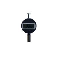
Durometer Hardness is used to determine the relative hardness of soft materials, usually plastic or rubber. The test measures the penetration of a specified indentor into the material under specified conditions of force and time. The hardness value is often used to identify or specify a particular hardness of elastomers or as a quality control measure on lots of material. STECH ENGINEERS manufacturing various model of Hardness Testers for the accurate measurement of Hardness of the vulcanized rubber, plastic, ebonite, fiber and all other soft and hard elastomers as per lates American standard ASTM D 2240 and German standard DIN 53505 and other International standards.
| Simple and easy to use key lock to avoid accidental calibration. | |
| Inhouse calibration facility provided | |
| Separate hand probe with extended cable for easy and comfortable testing. | |
| Peak value hold and store in memory upto 9 test or more | |
| Large LED display for clear vision. | |
| Very light weight probe for quick and accurate application on specimen. | |
| Battery and power operated to use inhouse and outdoor test requirements. | |
| Standard carry-bag with all test and guarantee certificates. | |
| Technical Specification | Shore A ( for Soft elastomers & Soft rubber ) |
Shore D ( for Hard elastomers & Hard rubber ) |
|
Reading range |
0 to 100 shore unit |
0 to 100 shore unit |
|
Operating Temperature |
0 to 40 deg C |
|


| Peel or adhesion testing is the measurement of the adhesive or bond strength between two materials. It is performed by applying a tension load to the materials on one of three different ways: | |
| Pullingtwo flexible materials axially away from each other forming what is called a 'T' peel | |
| Pulling a flexible material away from a non-flexible material or substrate, both held vertically, forming what is called a 180 degree peel | |
| Pulling a flexible material away from a non-flexible material or substrate, which is held horizontally, forming what is called a 90 degree peel |
For example separating the backing from an adhesive bandage would be a 'T' peel, pulling the back of a blister pack of tablets would be either a 90 degree or 180 degree peel and pulling the seal from the top of a yoghurt pot would be a 90 degree peel. There are varying degrees of flexibility and shapes creating a wide range of variations of these three basic peel types, requiring a variety of test grips and fixtures.
Benefits of Peel/Adhesion Testing| Ensuring the integrity and safety of products | |
| Ensuring the proper functioning of adhesive seals e.g. openability | |
| Reducing material costs and achieving lean manufacturing goals | |
| Compliance with industry standards |
Standards
A number of standards for testing adhesives seals ad bonds have been developed, such as:
| ASTM D1876 - 08 Standard Test Method for Peel Resistance of Adhesives (T-Peel Test) | |
| BS EN 1895:2001 Adhesives for Paper and Board, Packaging and Disposable Sanitary Products. 180 Degrees. 'T' Peel Testfor a Flexible-to-Flexible Assembly | |
| ISO 11607-1:2006 Packaging for Terminally Sterilized Medical Devices - Part 1: Requirements for Materials, Sterile Barrier Systems and Packaging Systems | |
| ISO 11339:2003 Adhesives - T Peel Test for Flexible-to-Flexible Bonded Assemblies |

The Tubular Impact Tester evaluates the coating resistance to impact. The procedure of Testing Methods briefly described in the International Standards. Stech Engineers Tubular Impact Tester is made with sturdy and heavy duty frame for base and easy clamping and depth adjustment.

| The Barcol Impressor is a simple, portable hardness tester that is used by industrial and commercial customers. The Impressor has been a standard in the industry for testing raw material or field testing of final products, such as fiberglass panels, plastic extrusions, aluminum profiles, and related materials. Compliant with the National Fire Protection Association, NFPA1932, the Impressor is a proven device for field testing of fire ladders after being exposed to high temperatures. | |
| Aluminum | |
| Aluminum Alloys | |
| Soft Metals | |
| Plastics | |
| Fiberglass | |
| Fire Department Ladders | |
| Composite Materials | |
| Rubber or Leather | |

A measure of the indentation resistance of elastomeric or rubber materials based on the depth of penetration of a ball indentor. An initial contact force is applied to an indentor and the penetration is set to zero. The force is increased to a specified total load and the depth of penetration is measured. The IRHD value is related to the depth of indentor penetration. For highly elastic materials, IRHD and Shore A are comparable. An IRHD value of 0 represents a material with an Young's Modulus of zero and an IRHD value of 100 represents a material with an infinite Young's Modulus. The relationship between the depth of penetration (hardness) and the IRHD number is based on: F/E=0.0038r0.65*D1.3.
where: F is the indentation force in Newtons, E is the Young's Modulus in MPa, r is the indentor ball radius in mm, and D is the depth of penetration in mm.
where: F is the indentation force in Newtons, E is the Young's Modulus in MPa, r is the indentor ball radius in mm, and D is the depth of penetration in mm.

STECH tearing strength Tester Determines the Tearing Strength of fabrics, papers, plastic films or other similar materials is determined by measurement of the work done in tearing through a fixed length of the test specimen using of Elmendorf Tear Tester. The Elmendorf Tearing Strength Tester consist a brass sector pendulum pivoted on anti-friction ball bearings on a vertical bracket fixed on a rigid metallic base. The test specimen in shape of arectangular piece held between two clamps, one of which is mounted on the pendulum and the other is mounted on the vertical bracket. The clamps are mounted in such a manner that their holding faces are aligned with each other when the pendulum is locked in its raised position. The pendulum is released by lifting a release lever. This action causes the test specimen to tear right through. The tearing strength is indicated on a scale fitted on the pendulum against a low friction pointer pivoted on the axis of the pendulum. An adjustable knife is also mounted on the bracket on which the pendulum and the fixed clamp is mounted. It is centered between the two clamps and is used for making the initial Cut in the test specimen. The apparatus is finished in metallic painting and bright chrome plating to give it corrosion resistant finish.Augmenting weights for increasing the range of the tester for testing high strength materials are available as optional accessories. Low strength materials can be tested by mounting multiple specimens at the same time.

| Yarn Tension Tester is manufactured in an easy to handle design light weight, highly precision, more accurate, getting direct reading of tension from the dial instead of doing calculations after getting indirect readings as in some other meters. The Instruments is suitable to check the tension of Yarn when high speed spinning & windings are being done. | |
| Common Range of Tension Meter | |
| Low Ranges | High Ranges |
| 2 25 gms. | 50 500gms. |
| 5 50 gms. | 100 1000 gms. |
| 10 100 gms. | 250 2500 gms. |
| 20 200 gms. | 500 5000 gms. |
| 30 300 gms. | 1000 10000 gms. |

Co efficient of friction tester designed to find both static and dynamic co-efficient of friction through a metal platform system. The platform is allowed to move at the specified speed through a drive mechanism, driven with the help of a screw driven by a geared fractional HP electric motor. A steel sled of specified size, weight and covered with a micro cellular rubber sheet is also provided. The smaller specimen is wrapped around the sled and the higher specimen is clamped to the top of platform. A load cell type dynamometer is provided for measuring force for moving the sled. Most suitable for checking the co-efficient of friction of rubber sheet, fabrics, leather, rexine, paper, thin films etc

| De Mattia Flex Tester, electrically operated with single phase motor provides information about the resistance of vulcanized rubber compounds, coated and treated fabrics to cracking when subject to flexing. Crack development in that part of the surface where stresses are set up during flexing, or if that part of the surface initially containing a crack, causes this crack to extend in the direction perpendicular to stress. This test also assesses the durability of material. The machine tests six specimens at a time. | |||||||||||||||
| STECH ENGINEERS Flexing Machines is used to test specially moulded samples for resistance to cracking or cut growth by repeated flexing. Flex testing is recommended when the flexing encountered in service is liable to simulate the action of the test. (e.g. tyre sidewalls). Cracking and cut growth increase with increasing cycles. The tester is stopped at intervals specified and the cracks evaluated. Two sets of grips on either side of the frame are reciprocated at constant frequency for a preset number of cycles controlled by a cycle counter. Samples are loaded so that they are flat when the grip are tightened and flexed but not elongated during tester operation. The range consists of 6 machines capable of handling 12, 24 or 36 samples in either an unheated cabinet or an oven with digital temperature control having a range of 60C to 150C. | |||||||||||||||
| Features | |||||||||||||||
| |||||||||||||||

STECH ENGINEERS Ross Flexing Machine allows one end of the test specimen to be clamped firmly to a holder arm while the pierced end is placed between two rollers that must permit a free bending movement of the test specimen during the test. During each cycle, the pierced area of the test specimen is bent freely over a 10mm ( 0.4in. ) diameter rod through a 90o angle. The machine operates at 1.7 + 0.08 Hz (100 + 5cpm ).
| Introduction | |||||||||
| A pierced strip test specimen is bent freely over a rod to a 90o angle and the cut length is measured at frequent intervals, to determine the cut growth rate. The cut is initiated by a special shaped piercing tool. The test gives an estimate of the ability of rubber vulcanized to resist crack growth of a pierced specimen when subjected to bend flexing. No exact correlation between these test results and service is implied due to the varied nature of service conditions. | |||||||||
| Procedure | |||||||||
| Measure and record the median thickness of the test specimen taken at three points across the width at the point of the cut. With the holder arm of the flexing machine in a horizontal position, clamp side by side the test specimens of the same making sure that the cuts are at the center point of the are of the rods. Lower the adjustable top rollers until they just touch the test specimen and lock in this position by means of the wing nuts. Permitting free travel of the test specimens between the rollers during the bending movement. Start the machine and record the number of cycles by the use of a counter. Make frequent observations, recording the number of cycles and the increase in cut length measured to the nearest 0.5mm for the purpose of determining the rate of increase in cut length. When observing cut growth, the holder arm shall be at an angle approximately 45o from the vertical. The test shall be continued until the cut length has increased 500%, that is, until the combined length of the cut and crack has increased to a total of 15.0mm ( 0.60in. ) or when 250kilocycles has been reached with slow cracking samples. In some cases the cut growth is not in a straight line as a continuation of the cut made by the piercing tool, and "star shaped " cracking may develop. In this event, the cut growth shall be measured as the length of the longest continuous crack, regardless of its direction. When it is necessary to stop operation of the machine temporarily, the holder arm shall be in a horizontal position, so that the test specimens remain horizontal while not being flexed. | |||||||||
| Report | |||||||||
| |||||||||