Our Products

It consists of a vessel mounted in a heating bath and fitted with a condenser for condensing the fumes. Receiver with drain valve can be added for receiving the condensate. The unit is available in vessel sizes of 20, 50, 100, 200, & 300 Ltr.and is suitable for operation under atmospheric pressure and full vacuum.
Optional items
| Reactor Cap. Ltr. |
Bath KW | Vapour Line | Condenser M 2 | Reference |
|---|---|---|---|---|
| 10 L | 2 | 50 DN | 0.2 | SFSDU 10 |
| 20 L | 3 | 80 DN | 0.35 | SFSDU 20 |
| 50 L | 4.5 | 100 DN | 0.5 | SFSDU 50 |
| 100 L | 6 | 150 DN | 1.5 | SFSDU 100 |
| 200 L | 9 | 150 DN | 1.5 | SFSDU 200 |
| 300 L | 10.5 | 225 DN | 2.5 | SFSDU 300 |

The unit has been designed to suit the customers requirement of a combination of versatile reaction/distillation or combination for pilot plant work.
This has a flexibility of working at atmospheric pressure as well as under vacuum.
The typical unit has a reaction vessel fitted with a metal heating/cooling bath having a facility for heating and cooling bath by means of heating/cooling Fluids as a media.
The Standard system is equipped with stirrer heaving mechanical seal, a packed column on the side neck of the vessel, reflux divider, coil type condenser and or receiver system having a product, cooler, vent, drain and vacuum valves, Option of speed variation by mechanical variator or electronic variator can be provided.
The receiver system is equipped with product cooler. Vent/vacuum valve and drain valve.
The above unit are available in 10 Ltr., 20 Ltr., 50Ltr., 100 Ltr., 200 Ltr. & 300Ltr capacity with a spherical reactor.
Optional Items
Reactor Capacity
| Bath KW | Addition Vessel | Vapour Line | Condenser HTA M 2 |
Cooler HTA M2 |
Receiver Size | Reference | |
|---|---|---|---|---|---|---|---|
| 10 L | 2 | 2 L | 50 DN | 0.2 | 0.1 | 2L, 2L | SFFRU 10 |
| 20 L | 3 | 2 L | 80 DN | 0.35 | 0.1 | 2L, 5L | SFFRU 20 |
| 50 L | 4.5 | 5 L | 100 DN | 0.5 | 0.2 | 5L, 10L | SFFRU 50 |
| 100 L | 6 | 10 L | 150 DN | 1.5 | 0.35 | 10L, 20L | SFFRU 100 |
| 200 L | 9 | 20 L | 150 DN | 1.5 | 0.35 | 10L, 20L | SFFRU 200 |
| 300 L | 10.5 | 20 L | 225 DN | 2.5 | 0.5 | 20L, 20L | SFFRU 300 |

This unit is typically used for only distillation and fractionation under vacuum or at atmospheric pressure. The typical unit has distillation vessel fitted with a metal heating / cooling bath and with a packed column above reflux divider and coil condensers below are fitted on the packed column. Condensed material is either taken back to the vessel or to the receiver via product cooler.
The above units are available in 10 Ltr., 20 Ltr., 50 Ltr., 100 Ltr., & 200 Ltr.
Optional Items
| Reactor Capacity | Bath KW | Addition Vessel | Vapour Line | Condenser HTA M2 |
Cooler HTA M2 |
Receiver Size | Reference |
|---|---|---|---|---|---|---|---|
| 10 L | 2 | 2 L | 50 DN | 0.2 | 0.1 | 2L, 2L | SFFDU 10 |
| 20 L | 3 | 2 L | 80 DN | 0.35 | 0.1 | 2L, 5L | SFFDU20 |
| 50 L | 4.5 | 5 L | 100 DN | 0.5 | 0.2 | 5L, 10L | SFFDU 50 |
| 100 L | 6 | 10 L | 150 DN | 1.5 | 0.35 | 10L, 20L | SFFDU 100 |
| 200 L | 9 | 20 L | 150 DN | 1.5 | 0.35 | 10L, 20L | SFFDU 200 |
| 300 L | 10.5 | 20 L | 225 DN | 2.5 | 0.5 | 20L, 20L | SFFDU 300 |

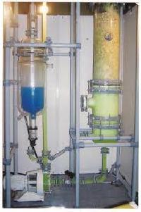
Hydrogen Chloride gas produced as a by product can be economically processed into Hydro Chloric Acid by simple Absorption Adiabatic Absorption is the most effective means of production of Hydro Chloric Acid solution. Under normal operating conditions Hydro Chloric Acid Solution of 30% 31% strength can be obtained.
These absorbers operate, as the name implies, without any heat input into the reaction zone.
The gas loading should in no case fall below 50% of the design maximum for adiabatic absorption column to be most effective means of absorption.
In this process HCL Gas is absorbed by fresh water flowing down the column . The heat generated by this reaction vapourises approximately 30% of the water that rises to the head of the column with non soluble components of the gas stream.
Hydrogen Chloride streams containing air, water vapour & non condensable are condensed / absorbed within the column and are returned together with the make up water to the bottom of the column through several packed sections and are passed through heat exchangers for dissicipatcing the heat of absorption before storage. The acid out let temperature is 45 C to 50.


The Falling Film Absorber are typical Heat Exchangers with weir tube arrangement at the top which is always Vertically Mounted.
A co current flow of gas & absorbent liquid flows down through the tubes each tube functioning as an individual heat exchanger. The Heat of absorption released is removed by the cooling water flowing in the shell side of the falling film unit. There by affecting gas absorption at lower temperatures and enabling a higher absorption rate.
Objectives : DESIGN")
Reaction systems are developed to fulfil the actual needs of chemical and pharma industry. Sigma Reactors are built for batch and semi batch operation mode, with perfectly matched components and quality materials. Conforming to GMP / FDA Guidelines and Explosion proof installations.
Glass Single Wall, Glass Double Wall, Glass Triple Wall Reactor, Glass Reactor with SS Jacket, Glass Lined Reactor with Glass top and Glass Lined Reactor

Bromine being a highly reactive material, finds wide application in many chemical industries like: Organic Intermediates, Dyestuffs, Agro chemicals, Fire Retardants etc.
During Bromingation not more than half the bromine added ends up in the reaction. The rest being rejected / discarded as bromides Bromides generally are
We can get Bromine in crude form from any of the Bromides above in our Bromine Recovery Plants. This crude Bromine is then distilled to get Bromine of purity 99.50%.
We manufacture Bromine Recovery Plants having the capacity of handling large amounts of Bromides. We can also give system for Bromine Recovery from Sea Bitterns.
Salient Features: