Our Products

Rotary Distributor Valves - (RDVs) are Hydraulic or Pneumatic Rotary Joints
with certain Valving /Logic integrated into it to achieve certain specific functionality
like clamping , flushing etc based on the relative angular position of the rotating
Housing with reference to the Non Rotating centre shaft.
RDVs find application in Rotary Transfer machining systems using Rotary
indexing tables, where each operating station have Machining fixtures with
clamping / locating mechanisms which are to be operated by hydraulics /
pneumatics, in each work stations
The valve operates in such a way that the actuators on the workstation fixture,
which comes to the loading / unloading position will automatically get connected to a
suitable direction control valve through RDV enabling the operator to manually
unclamp, remove the finished job and load the new job and clamp. The Jobs will
remain clamped in the other working stations, till the specific fixture returns to the
Loading /Un loading position
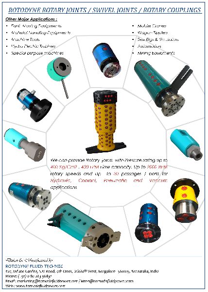
We design and manufacture rotary joints for various sectors like Machine tool,
Earth Moving , Construction, Hydro Power and Defence. Customised designs of
rotary joints are also offered and can handle upto
Operating Pressure - 400 Bar
Speed - 3000 RPM
No Of Passages - 30.
We also manufacturers Hydraulic Rotary Actuators & Hydraulic Orbital Motors, and
are the only indigenous manufacturer of Gerotor type Low Speed High Torque
Hydraulic motors as well as Zero Backlash Vane type Rotary actuators in India.

Industrial Hydraulic motorsconvert the energy in a pressurized hydraulic fluid into useful mechanical energy. Tornado hydraulic motors are fixed displacement low speed high torque hydraulic motors working on the proven orbit motor principle. The power generating element of this motors is a gerotor set with a lobed stator ring and a rotor with one lobe less than the stator ring. The rotor fits eccentrically inside the stator ring and together they form a number of chambers. In FMP series motors , the stator ring is a specially machined and matched component(fig.1). In other series, the stator ring lobes are formed by rollers located in precisely machined holes in stator rings.The pressurized oil enters the motor through the parts on the body and passes through a distributor valve driven by the rotor , which directs the oil sequentially to the oil chambers in the gerotor set. The pressure differential between these chambers causes the rotor to rotate. The rotary motion is transmitted to the output shaft as well as the distributor valve so as to produce a continuous rotary output. In FMP series motors the distributor valve is integral with the output shaft, whereas in other series, a hydrostatically balanced disc valve driven by an independent drive link is provided. This design facilitate short flow paths, higher efficiency, wear compensation of valve faces and longer life.
CHARACTERISTIC FEATURES
APPLICATIONS
Torando Hydraulic motors are ideally suited for Applications demanding vary high Torque at low or variable speeds, along with economy, compact size, reliability, maintenance-free service etc. These motors also provide a cost effective alternative to many other variable speed drives in vogue.
RECOMMENDED APPLICATION RANGES
| Hydraulic fluid | Mineral based Hydraulic oil |
| Fluid Temperature | 300c - 600c |
| Fluid Viscosity | 30cSt - 75 cST |
| Contamination level | 25 Micron Filtration of finer |
INSTALLATION
Tornado Hydraulic Motors can be fitted in ny desired position. If a drain line is connected , ensure that the motor case is always filled with oil.
DRAIN CONNECTION
All models of Tornado Hydraulic Motors are provided with built-in-check valves to limit the pressure on the shaft seal.
| FMP 50 |
FMP 80 |
FMP 100 |
FMP 160 |
FMP 200 |
FMP 250 |
FMP 300 |
|
| rev) | 50 | 80 | 100 | 160 | 200 | 250 | 300 |
| Speed (Max) (rpm) | 800 | 750 | 600 | 375 | 300 | 240 | 200 |
| Torque (Max) (Kg.M) | 6 | 10 | 13 | 21 | 23 | 25 | 25 |
| Flow (Max) (lpm) | 40 | 60 | 60 | 60 | 60 | 60 | 60 |
| Pressure (Max) (kg/cm2) | 100 | 100 | 100 | 100 | 90 | 75 | 65 |
| Output (Max) (Hp) | 4.5 | 6 | 6.5 | 6.5 | 6 | 5 | 4 |
| Length 'L' (mm) | 129 | 133 | 136 | 145 | 152 | 157 | 164 |
| Weight Kgs | 5.8 | 6 | 6.1 | 6.2 | 6.4 | 6.7 | 7 |


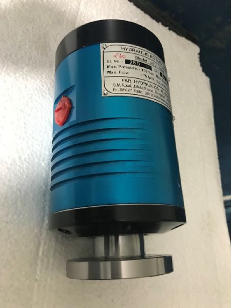
| Hydraulic Rotary Joints are used for conveying fluid under pressure from a stationary source to a to a rotating elements or Vice versa. They are also referred to as rotating unions, swivel joints etc. Our rotary joints are designed with sealing on the diameter or the rotating part and specific seal designs are selected based on the operating conditions like rotating speed, operating pressure , nature of application etc. This seal design has several distinct advantages over the contemporary face selling designs especially for high pressure low speed applications, like the possibility of having multiple ports which can be pressurized simultaneously, less susceptibility of fluid contamination, Higher pressure rating etc. Our rotary unions are available with maximum pressure rating of 350 Kg/cm2, speeds up to 3000 rpm and flow capacities up to 250 lpm.
HYDRAULIC ROTARY JOINTS
Major applications:
HIGH PRESSURE SWIVEL JOINTS
Major applications:
Specifications:
Major applications:
|
Model No |
Rated Pr. Kg / Cm2 |
Flow Rating lpm |
Speed rpm | No. of Ports |
Inlet Port connection |
Mounting | |
| Cont. | Peak | ||||||
| RTJ - 400 | 100 | 80 | 400 | 800 | 2 | 1/2" BSP | FLANGE |
| RTJ - 1000 | 100 | 80 | 1000 | 1500 | 2 | 1/2" BSP | FLANGE |