Our Products
Industrial Machinery
2 Products availableMeasuring Instruments & Equipment
1 Products availableTesting Services
1 Products availableTesting Equipments
1 Products availableMachine And Precision Tools
1 Products availableJigs, Casting Dies, Die Casting Moulds & Moulding Tools
1 Products availableWe offer a complete product range of Ross Flex Tester, Tearing Strength Tester, Demattia Flex Tester, Spark Tester and Hardness Tester(IRHD)
RISHIKESHRoss Flexing Machine allows one end of the test specimen to be clamped firmly to a holder arm while the pierced end is placed between two rollers that must permit a free bending movement of the test specimen during the test. During each cycle, the pierced area of the test specimen is bent freely over a 10mm ( 0.4in. ) diameter rod through a 90o angle. The machine operates at 1.7 + 0.08 Hz (100 + 5cpm ).
Introduction
A pierced strip test specimen is bent freely over a rod to a 90o angle and the cut length is measured at frequent intervals, to determine the cut growth rate. The cut is initiated by a special shaped piercing tool. The test gives an estimate of the ability of rubber vulcanized to resist crack growth of a pierced specimen when subjected to bend flexing. No exact correlation between these test results and service is implied due to the varied nature of service conditions.
Procedure
Measure and record the median thickness of the test specimen taken at three points across the width at the point of the cut. With the holder arm of the flexing machine in a horizontal position, clamp side by side the test specimens of the same making sure that the cuts are at the center point of the are of the rods. Lower the adjustable top rollers until they just touch the test specimen and lock in this position by means of the wing nuts. Permitting free travel of the test specimens between the rollers during the bending movement. Start the machine and record the number of cycles by the use of a counter. Make frequent observations, recording the number of cycles and the increase in cut length measured to the nearest 0.5mm for the purpose of determining the rate of increase in cut length. When observing cut growth, the holder arm shall be at an angle approximately 45o from the vertical. The test shall be continued until the cut length has increased 500%, that is, until the combined length of the cut and crack has increased to a total of 15.0mm ( 0.60in. ) or when 250kilocycles has been reached with slow cracking samples. In some cases the cut growth is not in a straight line as a continuation of the cut made by the piercing tool, and "star - shaped " cracking may develop. In this event, the cut growth shall be measured as the length of the longest continuous crack, regardless of its direction. When it is necessary to stop operation of the machine temporarily, the holder arm shall be in a horizontal position, so that the test specimens remain horizontal while not being flexed.
Report

Technical Specifications
RISHIKESHtearing strength Tester Determines the Tearing Strength of fabrics, papers, plastic films or other similar materials is determined by measurement of the work done in tearing through a fixed length of the test specimen using of Elmendorf Tear Tester. The Elmendorf Tearing Strength Tester consist a brass sector pendulum pivoted on anti-friction ball bearings on a vertical bracket fixed on a rigid metallic base. The test specimen in shape of a rectangular piece held between two clamps, one of which is mounted on the pendulum and the other is mounted on the vertical bracket. The clamps are mounted in such a manner that their holding faces are aligned with each other when the pendulum is locked in its raised position. The pendulum is released by lifting a release lever. This action causes the test specimen to tear right through. The tearing strength is indicated on a scale fitted on the pendulum against a low friction pointer pivoted on the axis of the pendulum. An adjustable knife is also mounted on the bracket on which the pendulum and the fixed clamp is mounted. It is centered between the two clamps and is used for making the initial Cut in the test specimen. The apparatus is finished in metallic painting and bright chrome plating to give it corrosion resistant finish.
Augmenting weights for increasing the range of the tester for testing high strength materials are available as optional accessories. Low strength materials can be tested by mounting multiple specimens at the same time.

De Mattia Flex Tester, electrically operated with single phase motor provides information about the resistance of vulcanized rubber compounds, coated and treated fabrics to cracking when subject to flexing. Crack development in that part of the surface where stresses are set up during flexing, or if that part of the surface initially containing a crack, causes this crack to extend in the direction perpendicular to stress. This test also assesses the durability of material. The machine tests six specimens at a time. RISHIKESH Flexing Machines is used to test specially moulded samples for resistance to cracking or cut growth by repeated flexing. Flex testing is recommended when the flexing encountered in service is liable to simulate the action of the test. (e.g. tyre sidewalls). Cracking and cut growth increase with increasing cycles. The tester is stopped at intervals specified and the cracks evaluated. Two sets of grips on either side of the frame are reciprocated at constant frequency for a preset number of cycles controlled by a cycle counter. Samples are loaded so that they are flat when the grip are tightened and flexed but not elongated during tester operation.

High Frequency Spark Tester consists of a Solenoid and an Interrupter which has natural High Frequency and when the current passes through the Solenoid, the hammer is attracted by its core, thereby breaking the circuit and at the same time charging the condenser. The hammer then springs back reforming the contact and allowing the condenser to discharge through an inductance of a few turns of thick wire of the Tesla Coil. This metal rod when brought within 1cm of the lining of the tank or any other vessel, produces a diffused Spray discharge, but if there is a minute crack, or microscopic hole in the lining, whether it be Glass or Rubber or PVC or any other insulation, this diffused discharge is concentrated into a bright spark passing through the hole or crack. This phenomenon is attributed to the fact that High Frequency current possess a very high tendency of taking the nearest passage to Earth. This method is therefore very useful in detecting faulty lining of vessels or tanks etc, or faulty insulation of cables, or for the detection of leaks and cracks in High Vacuum Systems, Scientific and laboratory glass apparatus
")
A measure of the indentation resistance of elastomeric or rubber materials based on the depth of penetration of a ball indentor. An initial contact force is applied to an indentor and the penetration is set to zero. The force is increased to a specified total load and the depth of penetration is measured. The IRHD value is related to the depth of indentor penetration. For highly elastic materials, IRHD and Shore A are comparable. An IRHD value of 0 represents a material with an Young's Modulus of zero and an IRHD value of 100 represents a material with an infinite Young's Modulus. The relationship between the depth of penetration (hardness) and the IRHD number is based on: F/E=0.0038r0.65*D1.35

Features
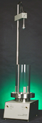
Integral leveling feet and "bulls eye" bubble - in - liquid glass level;
Height adjustable Pass/Fail Gauge;
Easy - to - read graduated scale, easily adjusts to specimen height;Portable, no power required;
Quality cast frame, stainless steel post and other durable components;
Rugged vinyl dust cover.

The Shore Round Style Durometer is the most widely used instrument throughout the world for evaluating the hardness of cellular, soft and hard rubber, and plastic material. It is small enough to be carried in the pocket and rugged enough to perform in the most hostile environment. The Round Durometer is designed to satisfy the industries needs for a basic, ASTM D2240-compliant unit with a scale graduated in increments of one durometer point. The analog durometer may be manually applied or, for better repeatability and accuracy, mounted on an applicable operating stand. Designed to meet a wide variety of applications, the Shore Analog Durometer is available in scales A, B, C, D, DO, E, O, OO, OOO-S and M.Specially designed Stands are used to improve the accuracy and reproducibility of both analog and digital durometer hardness tester readings by ensuring that the presser foot is exactly parallel to the specimen table. Any analog or digital durometer can be mounted on an applicable operating stand. The operating stand is primarily intended for use on a test specimen with parallel sides. Irregularly shaped objects may be tested in a nest or a fixture to make the given surface parallel to the durometer presser foot. ASTM D 2240 specifies three categories of operating stands: Type 1 are basic, manual operating stands. Type 2 is stands capable of controlling the rate of descent. Type 3 are hydraulically, pneumatically or electromechanical driven. Stands that fall into all three categories. For assistance in selecting the proper operating stand to fit your durometer.