Our Products
Milling Machines
2 Products availableCNC Machine
2 Products availableLathe Machines
2 Products availableCrusher, Shredder & Presses
1 Products availableMachine And Precision Tools
1 Products availableHydraulic Press
1 Products availableHydraulic Machines
1 Products available
| MODEL | ADMIT BETWEEN CENTRES | LENGTH OF BED | FLOOR SPACE OCCUPIED (M.M) | APPROX. WEIGHT IN KGS. NETT. GROSS | APROX. CASE DIMENSION (M.M.) | |
|---|---|---|---|---|---|---|
| VM-1 | 450 m.m. | 1370 m.m(4 ′-6") | 1650 × 970 | 575 | 625 | 1850 ×970 × 1500 |
| VM-2 | 725 m.m. | 1600 m.m(5 ′-3") | 1950 × 970 | 650 | 700 | 2150 ×970 × 1500 |
| VM-3 | 900 m.m. | 1830 m.m(6") | 2100 × 970 | 675 | 725 | 2300 ×970 × 1500 |

Body and all slides are made of high grade cast iron, duly seasoned, rigid & Strong enough to prevent dislortion & wear. Guide ways are Precision hand scraped/ground to match the corresponding surface of slides etc.
Table slide is hydraulically operated and the cross-slide is hydromecanically operated. Quick hydraulic retraction and forward movement of cross-slide is provided. The cut is taken by hand to avoid any damage to work piece and grinding wheel.
Work head is swivelling type to grind angular as well as conical jobs. The work spindle has been designed to suit live centre as well as dead centre grining
The machine is fully installed with electric motors, switch gears and wiring, normally arranged to suit the supply ol 4O01M0V.3 Phase AC, 50

The machine is built of heavy duty high grade cast iron. Base is built of hand scraped to achieve fine tolerance & accura"y. n""lprocatiop table provide V & Flat (guide) ways lining with TURCITE - B for easy movement.
Wheel HeadWheel head spindle hardned & ground, runs with precision angular'contact bearings with imported greece to have long trouble free service and driven by frange mounted motor through flexible couPlings.
The Microfeed systemWheel head - slide movement right side in the base. Wheel head feed

Raman Tools and cutter Grinder is a robust machine capable of dealing with a wide range of tools and Grinder operations. It is available as a steel cabinet mounted; machine is designed for the rapid sharpening of H.S.S. Milling Cutters, Cutters, Spiral Mills, Metal slitting sewer and face cutters, Reamers, Tap and with suitable attachments lathe tools and Mills formed cutter etc.
A totally enclosed wheel head motor with a double ended spindle carrier one standard and one extended wheel adaptor which can be mounted on either sand will receive both the cups and dish wheels supplied with the machine. The spindle, which runs at 2800RPM, is controlled by reversing switch built into the main body of the machine. The wheel is mounted on an engaged based plat which can swivel through 360 and can be hand wheel at the base of the machine. The column can be looked in any position and movement can be accurately controlled by means of friction mounted micrometry dial. The upper work table is provided with the slot which is not only serves as means of fixing the tooth rest etc. but also enables accurate location of the loose center heads. It is graduated either side of the zero setting and can swivel through 180 Provision is also made taper setting in inches per foot. Longitudinal movement of the table is obtained from a rack pinion operated by conveniently laced handle or if required can be operated by hand pressure only. The table is located on accurately machined vee and flat guide ways and is fitted with adjustable stops which can limit the movement of the table in and position. Crass Travers is accurately controlled by a hand wheel situated at the front of the machine which is fitted with a friction mounted dial.


The Sturdy construction of all passes guarantees stability and durability .The Press is provided within a 2 stage hand pump. The low pressure pump is used for a rapid advance of piston at low pressure. The high pressure pump is provided with a special material lining and is used for slow advance at high pressure.
This is provided for rising and lowering the table is smooth running. During operation the table is fastened by means of pin. The press has been all welded Standard accessories and planned off V block for straightenin
| TONS | BETWEEN COLUMN WIDTH AND LENGTH | BETWEEN RAM TO BED(MIN . & MAX.) | TRAVEL OF RAM (MM) |
|---|---|---|---|
| 5 | 500x125 | 75x600 | 100 |
| 10 | 600x150 | 75x600 | 125 |
| 15 | 650x150 | 75x600 | 150 |
| 25 | 800x300 | 180x910 | 180 |
| 40 | 950x350 | 180x910 | 190 |
| 50 | 1000x400 | 180x950 | 200 |
| 60 | 1050x450 | 180x975 | 200 |
| 75 | 1150x500 | 180x975 | 210 |
| 100 | 1200x600 | 180x975 | 225 |
| 150 | 1300x325 | 180x975 | 240 |

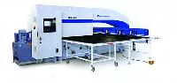
The MACHINE has automatic feeding arrangement in longitudinal, cross and vertical direction, having selection from different speeds. The millilg sprndle is fitted in two taper roller bearings. The different spindle speeds which are in geometrical progression are obtained by means of sliding gears, by u, hich only such gears come into mesh which are necessary for the desired speed. All the gears run in oil-bath the u'ear thus berng minimized.The table has a strong cross section and a coolant groove, fitted with a strainer at the draining point. The table screw has ph. bronze nut which minimizes wear and tear. The table screw is mounted on taper bearings which takes the axial load ofthe screw.
Table slide is hydraulically operated and the cross-slide is hydromecanically operated. Quick hydraulic retraction and forward movement of cross-slide is provided. The cut is taken by hand to avoid any damage to work piece and grinding wheel.The knee is well braced by internal partition walls giving it the greatest stability. In all respects, it has been carefully designed with wide slide surfaces which gives a rigid support to saddle and table. The vertical screw for raising & lowering the knee is provided with thrust bearings for talang the verlical load. The feed gear box is built on side of the knee. The base, which at the same time serves as a coolant tank is simple dimensioned and healy. The coolant pump and coolant pipes are so dimensioned that enough coolant is supplied to the cutter. The column owing to its special form is very n-uid and all guides are hand scraped.
| TABLE | INCHES | MM |
|---|---|---|
| Table Area | 48 × 11 | 1220 × 280 |
| No. of T Slots | 3 × 5/6 | 3 ×15 |
| Distance Between T Slots | 2 | 50 |
| Swivels forward & back | 45 ° |
| RANGE | ||
|---|---|---|
| Longitudinal Manual/automatic | 26 | 660 |
| Cross Manual only | 9 | 229 |
| Vertical Manual only | 16 | 406 |
| HEAD | ||
|---|---|---|
| Taper in Spindlenose | ISO 40 | |
| Dia of Spindlenose/at rear bearing | 3 1/2,13/4 | 80,44 |
| Size of hole through Spindle | 7/8 | 22 |
| Length ofArbor | 25 | 635 |
| Dia of Milling Arbor | 1 | 25.4 |
| Range of 9 Speeds | 60-830 RPM |
|
| OVERARM | ||
|---|---|---|
| Length of Overarm | 46 | 1168 |
| Width of bearing surface of ways | 2 | 50 |
| Max. Swing of tool dia | 11 | 279 |
| WORK RANGE | ||
| POWER FEED | ||
|---|---|---|
| Range of 3 Longitudinal feeds | 1-4 1/2 PM | 26-106 P/M |
| Head Motor | 2 HP/1440 RPM | |
| Coolant Pump Motor | 1/10 HP | |
| Weight of the Machine (packed) | 2200 Kg. | |
| WORK RANGE | ||
|---|---|---|
| Centre of spindle to top of table | 0-16 | 0-406 |

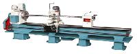
The VEEKY hacksaw Machine represents a progressive step forward in modern machine saw design.These amply proportioned and precision built machines will fulfill the, most arduous duties. The grouping of hydraulic controls and the range of speed and feeds makes the machines to cut quickly and efficiently all materials.
The speeds and drive by twin Vee belts.Main shaft and other shafts from the best steel.Regulators for instantaneously adjusting blade pressure.Hydraulic relief to saw blade on non cutting stroke.Automatic lifting of saw blade after cutting action.Gun-metal Bush in connected rod (fitted).Angular cutting attachment upto 45 degree of 7, 10, 12, 14, and 16, machines only (extra accessories).

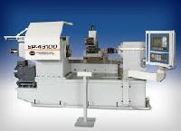
25 G Capstan Lathe With turret head axis vertical is specially designed for chuck work. It is a productive machine suitable for turning, drilling, boring reaming, facing & threading etc. with semi skilled operator. These machines are produced under the strict supervision of engineers having experience of more than three decades
Technical FeaturesCross Slide with two Tool Posts having independent stops.Six Speed oil immersed geared Head stock with double ended Multi-Disc friction Clutch.Hardened and Ground taper nose SpindleWell ribbed and hand scrape Bed
Standard Equipment and ElectricalsManual Tuuet:Cross Slide with two Tool Posts.One couplin 200 mm dia. Seven Spanners.
3 H.P. 1440 RPM Electric Motor, One Reversing Switch with Wiring