Listing ID #1022489
Company Information
Ask for more detail from the seller
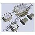
Contact SupplierWe are offering voltage surge protectors. Emi filter circuit design
to achieve adequate suppression of the spurious noise, filter style or circuit schematic should be first chosen following the rule of thumb of having the capacitor end of a filter facing the high impedance and the inductor end facing the low impedance. Table 2 below illustrates the above circuit selection criteria.
The next step will require determination of the working voltage, rated current, maximum dc resistance, cut-off frequency and insertion loss.
When specifying working voltage and rated current, any derating requirements should be taken into consideration. Maximum allowable voltage drop will usually govern maximum dcr of a filter. The cut-off frequency is often selected one decade above the frequency of a signal.
The insertion loss data throughout the catalog is based on mil-std-220 and provide means of comparison and testing only. Il performance of any given filter could be quite different for systems having actual source and load impedances other than 50 ohms.
To help the user get acquainted with this catalog and emi filter design, every effort has been made to organize the data sheets and list the parts in a logical order. Every table starts at the top with lowest voltagecurrent and consequently highest capacitanceinsertion loss characteristics parts. These are followed by higher voltage and naturally lower capacitance and insertion loss performance devices.
Our emi filter design catalog provides you with the most comprehensive and widely used selection of emi filters. However, it represents only a cross-section of capabilities. Whether your application requires unique electrical characteristics or customized mechanical configuration, there is a high probability that we will be able to satisfy your specific needs without compromise.

Connect with us