Company Information
Ask for more detail from the seller
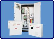
Contact SupplierLT APFC SYSTEM : - Reactive Power compensation system is designed to work automatically on LT power supply to measure , display & connect, disconnect the required capacitor banks through Thyristor /Capacitor Duty contactor with protection of MCB / HRC Fuses & series reactors to each bank to achieve the set Target power factor.
Thyristor /Contactor Switched Automatic power factor system is the highly accurate, properly designed system with required creep age distance as per required standards. APFC System equipped with advanced, Digital Microprocessor based relay to measure, calculate and display all electrical network parameters. It accurately measures cycle to cycle reactive power requirement for required capacitors are connected to switching element / device installed in the system, so as required capacitors are connected / disconnected to the network.
APFC Controllers close loop fast response multi method switching [MMS] algorithm helps system to have close & precise control on power factor.
APFC Relay has memory storage model of capacity 45 Days on hourly basis with Rs 232 port for communication.
Features :
Modular Structure
Protection to each step.
Well ventilated design.
Powder coated metallic frame structure design
Four modes of operation.
Door interlock Facility.
Good Service Backup.
Applications :
Automobile Industries, Cement Industries, Metal Industries.
Chemical & Fertilizer Plant, Pharmaceutical Industries.
Hospitals, Malls, Banks, IT Parks, Commercial Complexes.
Windmill, Power Stations, DG Stations, Crushers.
Railway / MES / Ordinance Workshops.
Display Parameters of Apfc relay :
Voltage, Current, Power Factor, Active Power (KW), Apparent Power (KVA) –All at LT Side.
Reactive Power (KVAR), Capacitive Reactive Power (KVAR)
Active Energy (KWH), Apparent Energy (KVAH), Reactive Energy (KVARH)
Real Time, Date, Network fault message display Capacitor bank status display, Load side Parameters viz. Current, P.F. & KVA.
Protections :
Controller offers protections in the following situations.
High Voltage, Low Voltage, Over-Load, Under-Load, Voltage Imbalance,
Load Current Imbalance, Over Capacitor Current, Capacitor Current,
Imbalance, Current spike, Over Temperature.
Programmable Parameters of APFC Relay :
Target Power Factor - 0.90 lead to 0.85 lag.
Time Delay (TD) – 1 mili sec to 255 sec
CT Ratio – Current Transformer ratio to measure actual load.
PT Ratio – Potential Transformer ratio to measure actual voltage.
No. of Steps – 1 to 16 Capacitor steps.
Capacitor Step Rating.[1Kvar to 1000 Kvar.]
Display Scroll time delay.
Capacitor’s discharge time.[ In mili Sec to Sec]
Compensation mode-fine-Average/minimum/maximum of Load Kvar basis.

Connect with us