

Company Information
Ask for more detail from the seller
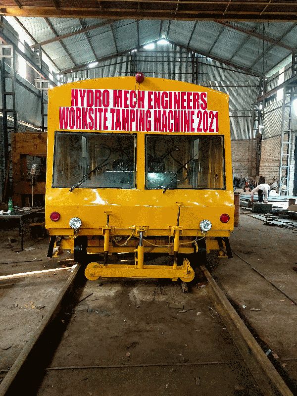
Contact Supplierspot tamping machine with all functions
performs all function of a full fledged tamping machine
to ensure track geometry is corrected, most tamping machines use a two chord lining system (one for vertical alignment and one for horizontal alignment). The two chord system requires three reference trolleys fitted to the machine - usually called a point, b point and c point. Some machines will use a fourth point between b and c to carry out quality control measurements.
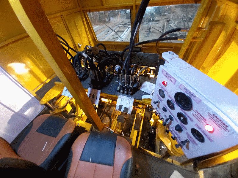
a point is always the front reference point and sits on uncorrected track. The anchorage for chords on a point are able to move to compensate for defects in track geometry - this is done by the "tower" operator. Depending on the chord system, the anchorages will be either a wire anchor or a light source.
b point is positioned as close as physically possible to the lifting lining unit. B point is used by the machine control system to position the track correctly using either potentiometers or optical filters, depending on type of chord system used.
c point is the rear-most measuring point and anchorage point for lifting and lining chords. Depending on type of chord system c point will be either wire anchor with a tensioning cylinder or a photoelectric light receiver.
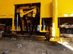
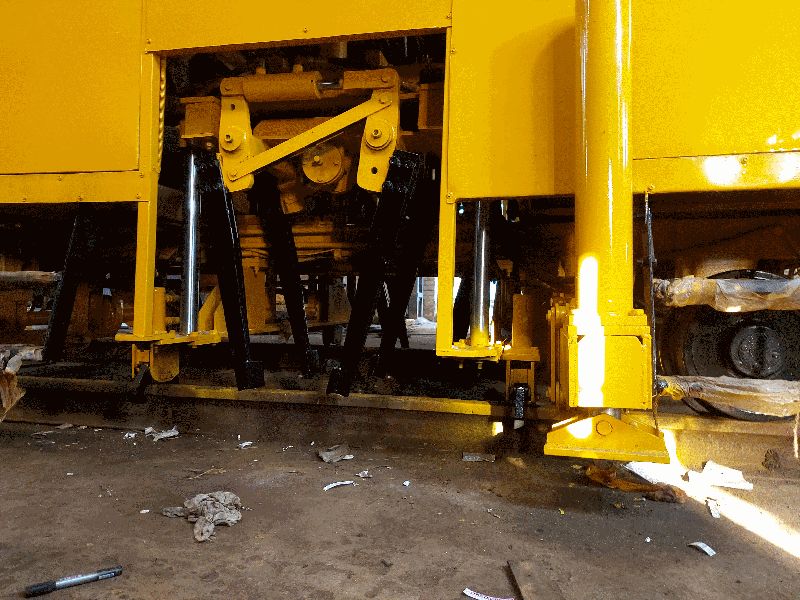
all three points are individual rail trolleys able to freely move up, down, left and right independent of the machine chassis and hence follow any minor fluctuation in rail position. When working, the machine uses pneumatic cylinders to lightly push these trolleys into the selected datum rail both vertically and horizontally.
when using this method, the tower operator positions a point anchorages according to existing track geometry measurements taken beforehand. Once a point has been positioned, it is then assumed that both a and c are in correct position as if machine were sitting on corrected track. The machine then uses the lifting lining unit to move the rail and b point in line with a and c.
tamping units
system 7 fully hydraulic tamping head
the tamping units of most tamping machines will consist of:
a set of tines either 8 or 16 per sleeper divided evenly between front and rear of sleeper
mounting or "guide" rods that allow the unit as a whole to move up and down in a linear motion
support frame
squeezing arms
tine mounts, can be either part of the squeezing arm or attached to it via a pin to allow swiveling depending on type of tamping machine
to generate the vibration needed for penetration and consolidation there are two leading methods commonly used:
using a hydraulically driven eccentric shaft attached either to the end of the squeezing cylinders or acting as the pivot point for the squeezing arms
using a special squeezing cylinder and valve assembly to oscillate the tines
a less common method more often seen on tamping head attachments for excavators is to use a motor driven vibrator assembly that is directly bolted to the support frame.

Connect with us