Listing ID #964090
Company Information
Ask for more detail from the seller
Contact SupplierThe washing machine having no automatic controls can be atomized to some extent by the circuit below. This is helpful in saving power and improving washing quality. In addition, it makes the homemaker free to do other chores while washing machine is doing its job. The timer gives audible warning continuously when the time is over.
About the circuit :
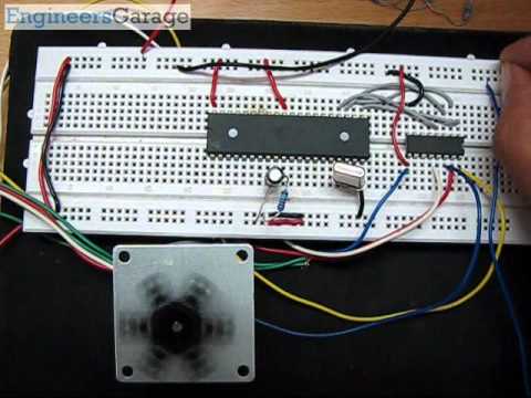
Washing Machine Timer is built around IC 4060 and inverting buffer 4049 both CMOS. Washing Machine Timer has on chip oscillator circuit, which can be finished by using external R, C components. C1, Rx*, R7 and VR1 forms the oscillator’s RC components which decides frequency and hence timing. C2, R11 provides power ON reset. Lower the frequency, higher the pulse timing. The oscillator frequency is divided by chain of 14 binary counters, which at the end of 14th stage, gives large pulse period at pin 3. Initially this output would be LO.
Once the circuit power is switched ON through S1, IC-1 gets reset and starts with all counter outputs reset to LO state. Counter outputs go Hi as counting progresses.
As the oscillator, frequency is divided and consecutive counter output goes high, the Hi state progresses through 14 stage counter outputs. LED D1 shows the oscillating behavior by pulsating flashes.
When last counter output (Q14 at Pin 3) switches Hi, transistor T1 conducts and counter input at pin 11 is pulled LO.
The output pin 3(last output of counter chain) is fed to the four inverting buffers (Ic 4049) which produces LO output at corresponding four outputs. Pin 2, 4 and 10 are connected in parallel to augment the drive capacity and drives a PZT buzzer. Fourth output at pin 6 drives the Relay through transistor T2 subsequently driving the washing machine through relay contacts.
Since initially 4049 output is Hi relay is energized as soon as power is applied to the circuit through S1. After the set time delay IC 4049 outputs go LO and relay is switched OFF thereby stopping the washing machine.
The time delay as per requirement can be selected by selecting resistor R1 to R6 with the help of rotary switch (one pole, 7way). Seven time delays are available to choose from. The time delay ranges can be altered by changing these resistance values.
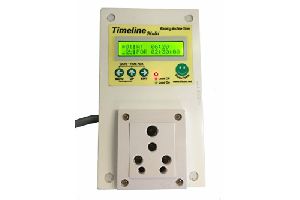
Select washing time bet.2 1/2 to 30 min. & buzzer when time laps.


Connect with us