Company Information
Ask for more detail from the seller
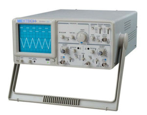
Contact SupplierAn oscilloscope is easily the most useful instrument available for testing circuits because it allows you to see the signals at different points in the circuit. The best way of investigating an electronic system is to monitor signals at the input and output of each system block, checking that each block is operating as expected and is correctly linked to the next. With a little practice, you will be able to find and correct faults quickly and accurately.
Feature:
High luminance, internal graticule CRT
Japanese electronic encoder,light,handy and reliable
Fully sealed long live vertical mode switch
ALT Triggering Function. Two independent signals
simultaneous observation
Build-in 6 Digit Frequency Counter
30MHz Dual Channel
10 times sweep magnification
TV Synchronization-Y mode
Specification
Horizontal System
Sweep time: 0.2uSec~0.5Sec/DIV,20steps in 1-2-5 sequence;
Sweep time accuracy:±3%
Vernier sweep time control:≤1/2.5 of panel-indicated &#118alue;
Sweep magnification: 10 times;
×10MAG sweep time accuracy: ±5% (20nSec~50nSec are uncalibrated);
Linearity:±5%,×10MAG: ±10% (0.2s~1us)
Position shift caused by ×10MAG: within 2DIV. At CRT screen center
X-Y MODE:
Frequency bandwidth: DC to at least 500KHz;
X-Y phase difference:≤3°at DC~50KHz
Sensitivity: Same as vertical axis. (X-axis:CH1 input signal; Y-axis:CH2 input signal.);
CALIBRATION VOLTAGE
Waveform: Positive-going square wave;
Frequency: Approx. 1KHz;
Duty ratio: Within 48:52;
Output voltage: 2Vp-p±2%;
Output impedance: Approx.1KΩ
CALIBRATION SIGNAL
Waveform: Positive-going square wave;
Frequency: Approx. 1KHz;
Duty ratio: Within 48:52;
Output voltage: 2Vp-p±2%;
Output impedance: Approx.1KΩ
CRT
Type: 6-inch rectangular type, internal graticule;
Phosphor:P31;
Acceleration voltage: Approx.2KV(20MHz)/Approx.12kv(40MHz);
Effective screen size:8×10DIV[1DIV=10mm(0.39in)];
Graticule: Internal;
Trace rotation: Provided
VERTICAL AXIS
Sensitivity:5mV~5V/DIV,10 steps in 1-2-5sequence
Sensitivity accuracy:≤3%
Vernier vertical sensitivity: Continuously variable to 1/2.5 or less of panel-indicated &#118alue Frequency
bandwidth: DC~30MHz(x5MAG:DC~7MHz)/DC~40MHz(x5MAG:DC~15MHz)DC~50MHz(X5MAG:DC~15MHz)
AC coupling: Low limit frequency 10Hz. (With reference to 100KHz, 8DIV, Frequency response with-3dB.)
Rise time: Approx.17.5ns (x5 MAG: Approx.50nS) Approx.8.75ns (x5 MAG: Approx.25nS)
Approx.7ns (x5 MAG: Approx.23.3nS)
Input impedance: Approx.1MΩ/Approx.25pF
DC balance shift: 5mV~5V/DIV: ±0.5DIV, 1mV~2mV/DIV ±2.0DIV
Linearity:1000:1 at 50KHz; >30:1 at 15MHz/>30:1 at 35MHz/>30:1 at 45MHz
CH2 INV BAL: Balanced point variation:≤1DIV (Reference at center graticule)
TRIGGERING
Triggering source: CH1,CH2,LINE,EXT
Coupling: AC: 20Hz to full bandwidth
SLOPE:+/-
Sensitivity: 20Hz~2MHz:1DIV, TRIG-ALT:2DIV EXT:200mV;TRIG-ALT:3DIV,EXT:800mV;
2~30MHz:1.5DIV;30MHz~40MHz:2.5DIV;40MHz~50MHz:3DIV;
TV: Sync pulse more than 1 DIV (EXT:1V)
Triggering modes: AUTO; NORM: TV-V: TV-H: (Both TV-V and TV-H synchronize only
when the synchronizing signal is negative)
EXT triggering signal input: Input impedance/: Approx:1MΩ/approx.25pF;
Max.input voltage:300V (DC+AC peak), AC: Frequency not higher than 1KHz

Connect with us