Products / Services
  • Products / Services
  • Companies
  • Buy Leads
    Post Buy Requirement

    Omni-VHZ Flow Transmitter

    • MOQ50 Piece
    • Nominal widthDN 8..25
    • Electrical connectionFor round plug connector M12x1, 5-pole
    • Ingress protectionIP 67 / (IP 68 when oil-filled)
    • Medium temperature-25..+80°C optionally -25..+120°C
    • Supply TypeExporter, Supplier
    • Preferred Buyer Location All over the world
    View More Details
    Send Enquiry

    Company Information

    • calendar Member Since 8 Years
    • building Nature of Business Retailer
    • gst icon GST No. 24CXWPP9877P1ZT

    Ask for more detail from the seller
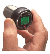
    Contact Supplier
    Report incorrect details
    • Product Details

    • Company Details

    no_img_icon

    • Nominal widthDN 8..25
    • SensorGearwheel volumeter
    • Medium temperature-25..+80°C optionally -25..+120°C
    • MakeHonsberg
    • Ambient temperature-20..+70°C
    • Supply voltage18..30 V DC
    • Process connectionG 1/4..G 1
    • Ingress protectionIP 67 / (IP 68 when oil-filled)
    • HysteresisAdjustable, position of the hysteresis depends on minimum or maximum
    • Power consumption< 1 W
    • Pressure lossSee upstream page
    • Repeatability±0.3 %
    • ConformityCE
    • Electrical connectionFor round plug connector M12x1, 5-pole

    Flow Transmitter / Switch OMNI-VHZ :

    • Flow sensor using the gearwheel principle
    • Suitable for viscous media (oils, emulsions)
    • Analog output 4..20 mA or 0..10 V
    • Two programmable switches (push-pull)
    • Graphical LCD display, backlit (transreflective), can be read in sunlight and in the dark
    • Modifiable units in the display
    • Programmable parameters via rotatable, removable ring (programming protection)
    • Full metal housing with non-scratch, chemically resistant glass
    • Rotatable electronic head for best reading position
    • Small, compact construction
    • Simple installation


    Characteristics :

    • The VHZ gearwheel flow meter measures the flow by a volumetric principle, in which a pair of gearwheels is moved proportional to the flow rate.
    • The movement of the gearwheels is measured through the enclosing housing wall by a sensor. The devices are suitable for viscous, fluid, self-lubricating media, as well as for aqueous fluids such as soaps, pasts, emulsions etc. which have a non-abrasive character. Because of the volumetric functioning principle, the devices are almost completely independent of viscosity.
    • The OMNI transducer located on the sensor has a backlit graphics LCD display which is very easy to read, both in the dark and in bright sunlight. The graphics display allows the presentation of measured values and parameters in a clearly understandable form. The measured values are displayed to 4 places, together with their physical unit, which may also be modified by the user. The electronics have an analog output (4..20 mA or 0..10 V) and two switching outputs, which can be used as limit switches for monitoring minimal or maximal, or as two-point controllers.
    • The switching outputs are designed as push-pull drivers, and can therefore be used both as PNP and NPN outputs. Exceeding limit values is signalled by a red LED which is visible over a long distance, and by a cleartext in the display. The stainless steel case has a hardened non-scratch mineral glass pane. It is operated by a programming ring fitted with a magnet, so there is no need to open the operating controls housing, and its leakproofness is permanently ensured.
    • By turning the ring to right or left, it is simple to modify the parameters (e.g. switching point, hysteresis...). To protect from unintended programming, it can be removed, turned through 180 ° and replaced, or completely removed, thus acting as a key.


    Option C : Preset Counter with external reset option, complementary switching outputs and actual value display.
    Option C1 : Instantaneous value display with analogue output, pulse-volume output and totalizer
    Handling and operation : The VHZ flow measurement device can be installed anywhere in the pipework system. A run-in section is not required. The direction of flow may be freely chosen. It should be ensured that no dirt particles (thread cutting swarf) can get into the flow space, as this could cause the blockage of the gearwheels. It may therefore be necessary to install filters upstream of the flow measurement device (mesh size 30 μm).
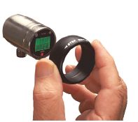

    Programming :
    The annular gap of the programming ring can be turned to positions 1 and 2. The following actions are possible :

    • The ring can be removed to act as a key, or turned through 180 ° and replaced to create a programming protector. Operation is by dialog with the display messages, which makes its
    • use very simple. Starting from the normal display (present value and unit), if 1 (STEP) is repeatedly selected, then the display shows the following information in this order :
    • Display of the parameters, using position 1
    • Switching value S1 (switching point 1 in the selected unit)
    • Switching characteristic of S1
    • MIN = Monitoring of minimum value
    • MAX = Monitoring of maximum value
      Hysteresis 1 (hysteresis value of S1 in the set unit)
    • Switching value S2
    • Switching characteristic of S2
    • Hysteresis 2 Code
    • After entering the code 111, further parameters can be defined:
      Filter (settling time of the display and output)
    • Physical unit (Units)
    • Output - 0..20 mA or 4..20 mA
      0/4 mA (measured value corresponding to 0/4 mA)
    • 20 mA (measured value corresponding to 20 mA)
    • For models with a voltage output, replace 20 mA accordingly with 10 V
    • Edit, using position 2 If the currently visible parameter is to be modified :
    • Turn the annular gap to position 2, so that a flashing cursor appears which displays the position which can be modified.
    • By repeatedly turning to position 2, values are increased; by turning to position 1, the cursor moves to the next digit.
    • Leave the parameter by turning to position 1 (until the cursor leaves the row); this accepts the modification.
    • If there is no action within 30 seconds, the device returns to the normal display range without accepting the modification.
    • The limit switches S1 and S2 can be used to monitor minimal or maximal. With a minimum-switch, falling below the limit value causes a switchover to the alarm state.
    • Return to the normal state occurs when the limit value plus the set hysteresis is once more exceeded. With a maximum-switch, exceeding the limit value causes a switchover to the alarm state.
    • Return to the normal state occurs when the measured value once more falls below the limit value minus the set hysteresis.The change to the alarm state is indicated by the integrated red
    • LED and a cleartext in the display. While in the normal state the switching outputs are at the level of the supply voltage; in the alarm state they are at 0 V, so that a wire break would also display as an alarm state at the signal receiver.


    Overload display : Overload of a switching output is detected and indicated on the display ("Check S 1 / S 2"), and the switching output is switched off.
    Simulation mode : To simplify commissioning, the sensor provides a simulation mode for the analog output. It is possible to create a programmable value in the range 0..26.0 mA at the output (without modifying the process variable). This allows the wiring run between the sensor and the downstream electronics to be tested during commissioning. This mode is accessed by means of Code 311
    Factory settings : After modifying the configuration parameters, it is possible to reset them to the factory settings at any time using Code 989.
    Options :

    • Counter C (hardware and software option)
    • Preset Counter with external reset option, complementary switching
    • outputs and actual value display (modified wiring diagram!)
    • Counter C1 (software option): Instantaneous value display with analogue output, pulse-volume output and totalizer


    Accessories :

    • Cable/round plug connector (KB...) see additional information “Accessories”
    • Device configurator ECI-1


    Download


    Download Detail File : Click Here
    Interested in this product? Ask for more details & Latest Price from seller
    Send Enquiry

    Product Images

    • Omni-VHZ Flow Transmitter
    • Omni-VHZ Flow Transmitter
    • Omni-VHZ Flow Transmitter
    Share your requirements for a quick response!
    Tell us what you need?

    By clicking Get Quotes Now, I accept the T&C and Privacy Policy.

    Looking for Omni-VHZ Flow Transmitter?

    Quantity
    Seller Contact Details
    Waiting for permission
    To search by voice, go to your browser settings and allow access to microphone

    Allow microphone access to search with voice