Listing ID #5192370
Company Information
Ask for more detail from the seller
Contact SupplierIt will have two units, free standing, floor mounting type made out of heavy gauge MS Sheet & painted with Primer & 2 coats of anti-corrosive paint.
One Unit :
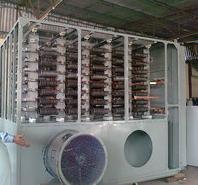
It will have two Compartments i.e. Contactor Panel & Resistance Box. The Contactor Panel will be dust & Vermin proof & will house required Power Contactors to switch ON & OFF the Resistance Banks to attain required speed. The Resistance Box will be well Ventilated type & will house Resistance Banks. The Grid Resistance units will be made of SS Punched plates with high thermal capacity and temperature-rise up to 300°C over an ambient of 50°C. The Resistance unit will be assembled in Banks with good porcelain & other insulated material. The construction & mounting of Resistance Banks will be easy to maintain & replace. The Resistance Box & Contactor Panel will be mounted back to back in one unit. The connection between the Resistance Box and Contactor Panel as well as between Resistance Banks & Power Contactors are done by copper flats of sufficient cross-section. It will be provided suitable rating Air Break Power Contactor (AC 3 duty) of ‘Reputed make’ (in delta connected) to suit the RA of motor. It will be suitable for controlling speed from 60% to 100% as 1.25% speed variation per step in total 32steps.
Second Unit :
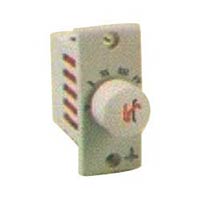
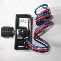
It will be Control Panel/Speed Selector Panel free standing, Floor mounting, dust & vermin proof. It will house the necessary control units like Aux. Contactors, Timers, Overload Relays, Indicating Lamps, Push Buttons etc. The Mini PLC used for setting of Logic controls of different speeds.
Construction :
Sheet Steel Clad, free standing, floor mounting type made out of 2mm. thick sheet with suitable angle iron reinforcement. The paint finish will be Light Grey 631 of IS:5. The Grid Resistance Regulator Panel basically comprises of 2 portions, the Resistor unit and the Contactor Panel. The Resistor unit is attached to the back of Contactor Panel and comprises Grid Elements assembled in the form of banks, stacked one above the other. All the Grids will be housed in this panel. The top will be covered with weld mesh only. Hot Air outlet ducting if required, has to be arranged at top by you. The Power Contactor Panel houses the Rotor Contactors suitably interconnected with adequately rated copper jumpers. A Bus Bar arrangement to connect 4-6Nos. Rotor Cables will be provided at bottom of panel with a suitable clearance from gland plate. The inter connection between Resistor Cubicle and Contactor Cubicle will be done through epoxy insulated wall mounted bushing sealed with gaskets. Proper heat shield arrangement will be made to see that heat transfer does not take place from Resistor Cubicle to Contactor Cubicle. The ‘make’ of Switch gear components will be of reputed make like C&S, L&T, GE, BCH, ABB, Siemens, TC etc.
Cooling Blowers :
Cooling Blowers are of either Axial or centrifugal type. The MS Impellers are balanced on a dynamic balancing machine to avoid vibrations. The air output will be as per the requirement of each equipment. While erection, the foundation has to laid separately for blowers and the foundation from blower to panel has to be made through canvas bellows. It is prevent the vibrations of blowers getting transferred to GR Panel.
Tests to be conducted :
1. Sequence/Operational-Functional Test as per Schematic/Wiring drawing. 2. Megger Test between Phase to Phase & Phase to Ground by 500 V megger. 3. High Voltage withstand test of 2.5KV for 1 minute on Control Circuit.


Connect with us