Company Information
Ask for more detail from the seller
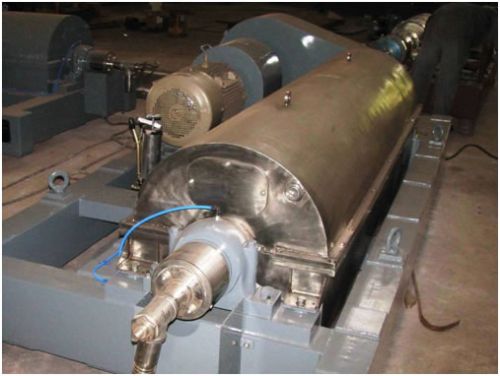
Contact SupplierMBE has in its product range, two types of environmental centrifuges, 2 Phase centrifuges & 3 Phase centrifuges.
Solid Bowl Centrifuges Co-Current design (2 Phase): The feed material is into solid bowl centrifuge with the aid of a pump. Progressive cavity pumps are commonly used for this duty, as they ensure a controlled uniform delivery of the feed. The feed rate may be ascertained with the aid of s flow meter in order to determine the throughput rate per hour or per day. The feed material is first pumped through a stationary feed pipe (1) into the feed compartment (2) which is located in the hub of the material screw conveyor (5) and within the field of centrifugal forces. The effect of these centrifugal forces causes the feed to flow through the feed compartment outlets (3) and into the bowl (4) of the solid bowl centrifuge.
The principal of co current flow starts the settling process as the feed enters at the large diameter end of the bowl. Solids and liquid are transported in the same direction. Hence, the complete bowl length is available for setting. This arrangement provides long settling distances and extended sedimentation time for the feed material to be dewatered or thickened. The settling operation proceeds uniformly, trouble free and with minimal turbulence.
The centrifugal force developed during normal operation causes the relatively heavy solid particles to settle on the bowl wall. These sedimented particles are transported inside the bowl by the screw conveyor (5) to the solids discharge point (7). Bowl and screw conveyor rotate in the same direction, but the screw conveyor speed slightly differs from that of the bowl. That differential speed is brought about by a suitable gearbox (6) by the corresponding transmission ratio of the V-belt drive, or through the utilization of s special hydraulic scroll drive system.
The separated solids are discharged through outlet openings (7) and are collected in casing (8). They are then routed through a chute to be discharged. The cent rate flows through the return channels (11) fixed to the conveyor hub in the opposite direction to that of the solids. The liquid leaves the centrifuge at the feed inlet end. This arrangement avoids interference with the sedimentation process, which normally occurs with the traditional countercurrent design.
The return channels for the cent rate discharge are sized so that the velocity of the flow substantially prevents the sedimentation of superfine solids contained in the cent rate against the interior walls of the channels. The cent rate is discharged over vertically adjustable weir plates (12) thus allowing for changes to be made to the cent rate level and consequently , altering the volume of the liquid retained inside the centrifuge. The cent rate is discharged through a chute. Visual inspection of the cent rate for the purpose of controlling the cent rate clarity is possible by taking samples at the machine outlet. Alternatively, provision can be made for automatic cent rate turbidity measurement and adjustment.
Type | Indicating Capacity (m3/hr) | Drive Motor | Max'G' Force | Max. Bowl Speed | Normal Size | Total Weight (kg) |
S0-1 | 1-2 | 7.5 | 2689 | 4400 | 250 x 750 | 850 |
S1-1 | 4-6 | 11 | 2247 | 3400 | 350 x 1050 | 1560 |
S1-11 | 8-12 | 18.5 | 2662 | 3700 | 350 x 1560 | 1900 |
S2-1 | 12-15 | 18.5/22 | 2175 | 2950 | 450 x 1350 | 2300 |
S2-11 | 20-25 | 22 | 1755 | 2650 | 450 x 1950 | 2570 |
S3-01 | 25-30 | 22/30 | 1425 | 2200 | 530 x 2270 | 3200 |

Connect with us