Products / Services
  • Products / Services
  • Companies
  • Buy Leads
    Post Buy Requirement

    Electric Linear Actuators

    • Supply TypeManufacturer, Exporter, Supplier, Retailer
    • Preferred Buyer Location All over the world

    A Electric Linear Actuators is a hardware which creates the movement along a straight line, in contrast with the rotary motion of a conventional electric motor. The linear actuator is used in....
    View More Details
    Send Enquiry

    Company Information

    • calendar Member Since 9 Years
    • building Nature of Business Retailer
    • Year of Establishment 2016

    Ask for more detail from the seller
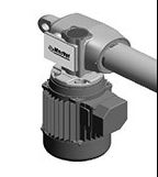
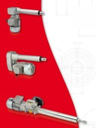
    Contact Supplier
    Report incorrect details
    • Product Details

    • Company Details

    no_img_icon

    A Electric Linear Actuators is a hardware which creates the movement along a straight line, in contrast with the rotary motion of a conventional electric motor. The linear actuator is used in automation, automotive (such as management carburetor, moving lights), in computer peripherals (disk drives and printers), valves and other areas of application where there is a linear motion.


    Electronic driver for 1 or 2 independent actuators or 2 synchronized actuators 12/24V 10-15A
    Features :

    • Driver power stage with pulse width modulation (PWM)
    • Customizable acceleration and deceleration ramps
    • Extreme precision and control for movement and brake
    • Current and temperature limits
    • Stop with limit switches
    • Parameters editable in an easy and fast way thanks to a PC interface and through a USB serial converter
    • Control of movements in synchronous mode by encoders with Hall effect; setting of the electronic limit switches (opening/closing)
    • Compatible with a wide range of products and different applications
    • High efficiency and low losses of power stage


    It is designed as electronic driver in low voltage for the control of one or two linear actuators with DC motors through MOSFET transistors with pulse width modulation (PWM). In “sync” mode, the driver ensures the balancing of actuators also in case of extremely different loads in terms of weight, shape,
    or distribution on the surface, allowing a stroke without any difference between the two actuators.
    Technical Data :

    • Power supply: 12 to 48 V DC, maximum ripple 20%
    • Output current: 15 A for motor, in duty cicle S3 - 30% - 10 minutes
    • PWM frequency 10 kHz
    • Stand by power consumption: 50 mA @ 24 V
    • 12 digital inputs (3 - 12 V): 8 for commands/limit switches, 4 for encoders (max 1 kHz), with operating logic programmable (positive/negative)
    • 2 digital outputs NPN open collector (max 50 mA - 24 V): one for the fault and one programmable
    • Dimensions :
      • Without heat sink for currents up to 10 A: 86x72x30 mm (WxHxD)
      • With heat sink for currents over 10 A: 86x72x50 mm (WxHxD)


    Signal Terminals (Vertical)

    • Open: opening command
    • Close : closing command
    • Trim-1 : enabling independence for actuator 1
    • Trim-2 : enabling independence for actuator 2
    • OP-SW: opening limit switch
    • CL-SW: closing limit switch
    • INT-SW: intermediate limit switch
    • Stop
    • Encoder motor 1 – channel 1
    • Encoder motor 1 – channel 2
    • Encoder motor 2 – channel 1
    • Encoder motor 2 – channel 2
    • Digital output 1: Fault
    • Digital output 2: programmable
    • GND for commands, limit switches and encoder
    • +12V for encoder supply


    Power Terminals (horizontal) +V: positive supply 0V: GND :

    • M1+: actuator 1, positive supply (voltage > 0 opening)
    • M1-: actuator 1, GND
    • M2+: actuator 2, positive supply (voltage > 0 opening)
    • M2-: actuator 2, GND


    Main Controls

    • Open/Close: synchronous movement
    • Trim1 + Open/ Close : movement of actuator 1
    • Trim2 + Open/ Close : movement of actuator 2
    • Trim1 + Trim12 (3 sec): homing


    Homing : The driver moves both the actuators in the same direction, according to an adjustable profile, amperometric threshold (controlled mechanical stop) or limit switches, depending on the configuration. It detects automatically the connection’s direction of encoders


    Trimming : The driver moves each actuator independently, for mechanical adjustments and a first manual alignment. It is required to check that commands correspond to the direction of movement
    Possibility to configures on/off delays and reverse the logic.

    • The start is provided through fully adjustable voltage ramps.
    • The stop is provided through electronic limit switches (or eventually mechanical limit switches), or with adjustable current limits.


    Signal Terminals (vertical) :

    • Open-1: opening command for actuator 1
    • Close-1: closing command for actuator 1
    • Open-2: opening command for actuator 2
    • Close-2: closing command for actuator 2
    • OP-SW-1: opening limit switch for actuator 1
    • CL-SW-1: closing limit switch for actuator 1
    • OP-SW-2: opening limit switch for actuator 2
    • CL-SW-2: closing limit switch for actuator 2
    • INT-SW-1: intermediate limit switch 1
    • INT-SW-2: intermediate limit switch 2
    • Stop-1: stop for actuator 1
    • Stop-2: stop for actuator 2
    • Digital output 1: FAULT
    • Digital output 2: programmable
    • GND for commands, limit switches and encoder
    • +12V for encoder supply


    Power Terminals (Horizontal) +V: positive supply 0V: GND :

    • M1+: actuator 1, positive supply (voltage > 0 opening)
    • M1-: actuator 1, GND
    • M2+: actuator 2, positive supply (voltage > 0 opening)
    • M2-: actuator 2, GND


    In case of one or two independent actuators :

    • It is possible to use intermediate limit switches
    • It is possible to configures on/off delays and reverse the logic
    • The start is provided through fully adjustable voltage ramps
    • The stop is provided through mechanical limit switches, limit switches for overcurrent or adjustable current limits


    Main editable parameters:

    • Voltage ramps
    • Current limits
    • Synchronous or independent enablement
    • Homing at the start (for sync only)
    • Homing with current limits or limit switches (for sync only)
    • Virtual limit switches settled with encoder pulses limits (for sync only)


    Values monitorable through “Monitor” and “Statistics” sections :

    • Motors current
    • Applied voltage
    • Temperature
    • Speed
    • Active commands
    • Operating mode
    • General information about the operating status of the driver


    Using the PC interface, it is possible to :

    • Consult the errors history (the driver stores each error and the time at which it occurred, from the last start)
    • Decide if an error stops the operation (only advanced mode for some errors)
    • Decide after how many repetitions of the same error the driver has to block (only advanced mode for some errors)
    • Decide the error tripping delay (only advanced mode for some errors)


    The connection driver/PC is possible through an USB/UART cable converter.


    Graph


    Download Detail File : Click Here

    Description

    CodeNameDescription
    PF.0104MC12/10A/SElectronic driver for 2 synchronized actuators (max 10A)
    PF.0105MC12/10A/IElectronic driver for 2 independent actuators (max 10A)
    PF.0106MC12/15A/SElectronic driver for 2 synchronized actuators (max 15A)
    PF.0107MC12/15A/IElectronic driver for 2 independent actuators (max 15A)
    PF.0102CAVO AZ2 CONVERTUSB/UART cable converter for the interface

    Product Images

    • Electric Linear Actuators
    • Electric Linear Actuators
    • Electric Linear Actuators
    Share your requirements for a quick response!
    Tell us what you need?

    By clicking Get Quotes Now, I accept the T&C and Privacy Policy.

    Looking for Electric Linear Actuators?

    Quantity
    Seller Contact Details
    Waiting for permission
    To search by voice, go to your browser settings and allow access to microphone

    Allow microphone access to search with voice