Listing ID #4646536
Company Information
Ask for more detail from the seller
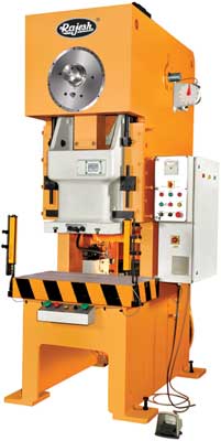
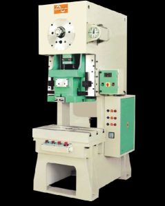
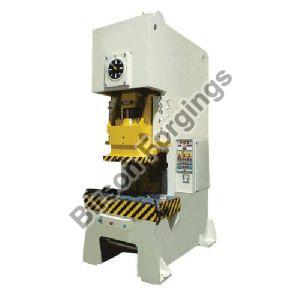
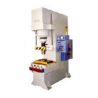
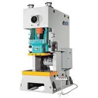
Contact SupplierKeeping ourselves abreast of sophisticated process technology, we manufacture high standard cross shaft presses, that are popular amidst our clients for uncompromising quality and high functionality. These presses are available in a rigid steel configuration, which keeps the stress & deflection within the permissible limits and ensures the maximum strength even unber the highest load. Shaft of these presses is ground finished on bearing surfaces. These presses undergo testing prior to dispatch to our clients. We also entertain the clients’ queries to customize our range as per their specifications.
Features :
The salient features of our cross shaft presses are mentioned below: High Performance Resistant to corrosion Low power consumption High tensile strength Easy maintenance
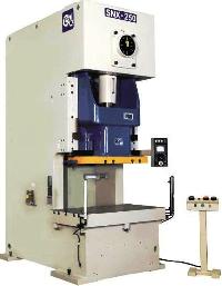
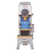
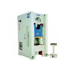
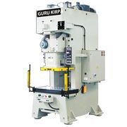
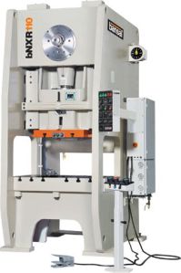
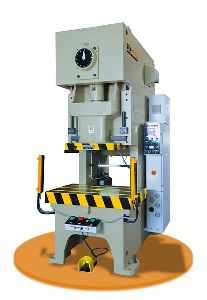
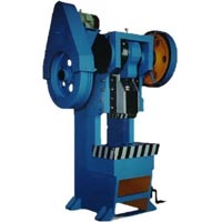
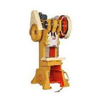
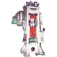
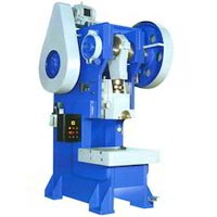
Cross Shaft Power Presses :
We manufacture engineered pressing machines, cross shaft machine with following features.
Features :
Fully enclosed drive Front stroke adjustment Large slide face & bed area Hhr Gears operating in oil bath Compact & rigid construction Widely spaced long gibs hold slide in accurate alignment
| Model | RX-25 | RX-35 | RX-45 | RX-60 | RX-80 | RX-110 | RX-160 | RX-200 | RX-250 | ||||||||||||||||||||||||
| S | H | P | S | H | P | S | H | P | S | H | P | S | H | P | S | H | P | S | H | P | S | H | P | S | H | P | |||||||
| Capacity | 25 | 35 | 45 | 60 | 80 | 110 | 160 | 200 | 250 | ||||||||||||||||||||||||
| Length of Stroke (D)mm |
80 | 50 | 35 | 90 | 60 | 40 | 110 | 70 | 45 | 130 | 80 | 50 | 150 | 100 | 60 | 180 | 110 | 70 | 200 | 130 | 80 | 220 | 150 | 90 | 250 | 180 | 110 | ||||||
|
90 | 110 | 140 | 80 | 100 | 130 | 70 | 90 | 120 | 60 | 80 | 100 | 60 | 80 | 100 | 50 | 70 | 90 | 40 | 60 | 80 | 35 | 50 | 65 | 30 | 45 | 55 | ||||||
| 70 | 80 | 80 | 60 | 70 | 80 | 50 | 60 | 80 | 40 | 55 | 70 | 40 | 50 | 65 | 35 | 45 | 60 | 30 | 35 | 50 | 25 | 30 | 40 | 22 | 30 | 30 | |||||||
| | | | | | | | | | | | | | | | | | | | | | | | | | | | | | | | | | | | | | | | | | | | | | | | | | | | | | | |||||||
| 110 | 140 | 180 | 95 | 130 | 170 | 85 | 120 | 160 | 75 | 110 | 150 | 75 | 100 | 140 | 65 | 90 | 125 | 50 | 70 | 100 | 45 | 60 | 85 | 40 | 50 | 70 | |||||||
| Tonnage Rating Point (B.D.C.)mm |
3.2 | 2.3 | 3.2 | 2.3 | 3.2 | 2.3 | 4 | 2.3 | 5 | 3.2 | 5 | 3.2 | 6 | 4 | 6 | 4 | 6 | 4 | |||||||||||||||
| Die Height (D.H)mm |
230 | 200 | 200 | 250 | 220 | 220 | 270 | 240 | 240 | 300 | 270 | 270 | 330 | 300 | 300 | 350 | 320 | 320 | 400 | 360 | 360 | 450 | 400 | 400 | 450 | 400 | 400 | ||||||
| Adjustment of Slide (G)mm |
50 | 50 | 60 | 70 | 80 | 90 | 100 | 110 | 120 | ||||||||||||||||||||||||
| Area of Slide (PxQ)mm |
330×250 | 380×300 | 430×350 | 480×400 | 560×460 | 650×520 | 720×580 | 860×650 | 960×720 | ||||||||||||||||||||||||
| Diameter of Shank Hole mm |
Ø38.1 | Ø50.8 | Ø50.8 | Ø50.8 | Ø50.8 | Ø50.8 | Ø65 | Ø65 | Ø65 | ||||||||||||||||||||||||
| Area of Bolster (ExF)mm |
700×320 | 780×400 | 840×440 | 900×520 | 1050×600 | 1150×680 | 1250×760 | 1400×840 | 1500×900 | ||||||||||||||||||||||||
| Thickness of Bolster (T)mm |
85 | 100 | 115 | 130 | 140 | 155 | 165 | 180 | 180 | ||||||||||||||||||||||||
| Height of Bolster (Z)mm |
800 | 800 | 800 | 900 | 900 | 900 | 900 | 1000 | 1000 | ||||||||||||||||||||||||
| Inside Measurement frame (R)mm |
394 | 490 | 516 | 544 | 610 | 670 | 730 | 900 | 970 | ||||||||||||||||||||||||
| Motor Floor Side Adjustment HPxP |
- | - | - | 0.5×4 | 0.5×4 | 0.5×4 | 1×4 | 1×4 | 1×4 | ||||||||||||||||||||||||
| Foot Size (AxB)mm |
750×1058 | 830×1125 | 890×1210 | 940×1315 | 1050×1480 | 1160×1680 | 1300×1985 | 1480×2113 | 1560×2400 | ||||||||||||||||||||||||
|
5x4 | 5x4 | 5x4 | 7 1/2x4 | 10x4 | 10x4 | 15x4 | 20x4 | 25x4 | ||||||||||||||||||||||||
| 5x4 | 5x4 | 7 1/2x4 | 10x4 | 10x4 | 15x4 | 20x4 | 25x4 | 30x4 | |||||||||||||||||||||||||
| Motor for side adjustment HPxP | 5X4 | 5X4 | 5X4 | 7 1/2X4 | 10X4 | 10X4 | 15X4 | 20X4 | 25X4 | ||||||||||||||||||||||||
| Foot size (AxB)m.m. | 5X4 | 5X4 | 7 1/2X4 | 10X4 | 10X4 | 15X4 | 20X4 | 25X4 | 30X4 | ||||||||||||||||||||||||
| Position of Anchor Bolts(MxN)mm |
620×860 | 730×925 | 790×1010 | 840×1115 | 950×1230 | 1060×1380 | 1180×1655 | 1360×1755 | 1440×2000 | ||||||||||||||||||||||||
| Floor Space Required(WxLxH)mm |
893×1280×2060 | 1000×1410×2180 | 1053×1490×2340 | 1100×1600×2540 | 1212×1820×2750 | 1325×2020×2985 | 1445×2325×3315 | 1625×2455×3715 | 1705×2790×3982 | ||||||||||||||||||||||||
| Accuracy | CNS 1st | CNS 1st | CNS 1st | CNS 1st | CNS 1st | CNS 1st | CNS 1st | CNS 1st | CNS 1st | ||||||||||||||||||||||||
Die Cushion (Option)
| Capacity | 2.2 | 2.2 | 3.5 | 3.5 | 6 | 8 | 10 | 14 | 14 |
| Length of Stroke mm | 50 | 50 | 70 | 70 | 80 | 90 | 100 | 110 | 120 |
| Area of Pad mm | 300×210 | 300×210 | 340×234 | 340×234 | 410×260 | 480×320 | 540×340 | 640×440 | 740×540 |


Connect with us