
Company Information
Ask for more detail from the seller
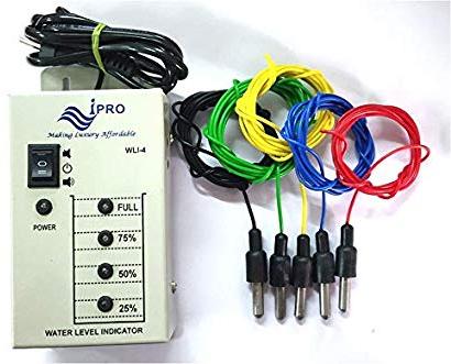
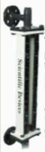
Contact SupplierThe name of the Liquid Level Indicator Without Alarm itself suggests its application. Liquid Level Indicator can be used for level control in hydro culture project. Also, it can be used for detecting the level of water in washing machine. The main feature of Liquid Level Indicators is that it shows each level in meaningful English letters. Liquid Level Indicator displays letter ‘E’ for Empty, ’L’ for Low, ’H’ for Half, ’A’ for Above Average and ‘F’ for Full Tank. The sensors for each level are immersed in tank. Their other ends are interconnected through four NOR gates, which uses IC1. The output is then given to IC2, which is BCD to seven- segment display driver IC. The level of fluid is indicated on 7- segment display.
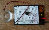
About the Circuit :
As shown in the circuit diagram, according to the level of liquid in tank, IC1 triggers each NOR gate. The output of each NOR gate in IC1 is applied to BCD input of IC2. When tank is low, the logic of four NOR gates in IC1 gives BCD logic as 1010. Their logics are applied to BCD inputs of IC2. Hence, IC2 drives 7- segment display according to the BCD Code present at inputs. For low level BCD logic is ‘1010’. For this logic, display will indicate ‘L’. As the level increases, BCD logic changes, and display will indicate accordingly. That is ‘H’ for half and ‘A’ for above average. You can see the code generation table or logic table.
Note that there is no display pattern like ‘E’ or ‘F’ available from IC2. Therefore, to obtain these pattern transistors T1 and T2 are used. These transistors blank out the unnecessary segments from 7- segment display. It can be seen that the letter ’E’ is generated by blanking ‘b’ and ‘c’ segments while it decodes digit ‘8’. Letter ‘F’ is obtained by blanking segment ‘b’ while it decodes letter ‘P’.
Note :
Liquid Level Indicator should not be used with inflammable or highly reactive fluids.


Connect with us