Listing ID #961490
Company Information
Ask for more detail from the seller
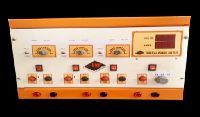
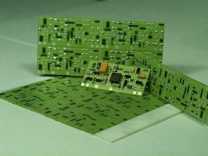
Contact SupplierElectronic Toss-Up allows users start the toss by simply pushing ON the switch S2 for reset and then S1 for start. The three LED’s will flash randomly and stop at some point glowing one of them finally. Our valued clients can avail Electronic Toss-Up in different specifications at economical price.
About the Circuit :
IC 555 is used to generate clock pulse of settable frequency with the help of VR1. R1, R2, R3, and C1 are used store charge in C1 when you press S1. The charge stored in C1 depends upon the time for which the switch S1 is pressed. The circuit goes on operating till the charge on C1 goes below the trigger level of 555. Resistor R2 helps in discharging C1 when it is at the threshold level and thus avoids false glow by noise.
The circuit is supposed to activate upon press of a push switch S1.As soon as this is pushed ON, Capacitor C2 start charging from zero level. Output pin 3 switches to HI State by virtue of pin 2 (trigger) being LO. IC4029 UP/DN counter is programmed to count down, decade mode ( by pulling down pin 10 and 9 respectively). At the first clock from pin 3 of 555, the IC 4029 clocks and outputs 2, 14, 11 & 6 go to zero state. Upon switching S2 ON, input states are loaded into outputs (2, 14, 11, 6) .The IC 4028 (one of 10 decoder) decodes and output Q0 goes Hi. On subsequent pulses from 555 the outputs Q2 to Q9 go HI one by one. The outputs are grouped in four, two, and four to glow LED Green, Yellow, and Red. The grouping is done randomly so that LEDs Grn, Yellow and Red glow at subsequent pulses from 4028 and appear random. Diodes connected to each group (e.g. D1, D2, D3, and D4) forms an OR gate which enables LED to glow even if one of the output from each group is Hi. Resistance R8 is provided to limit LED current.


Connect with us