Listing ID #4923809
Company Information
Ask for more detail from the seller
Contact Supplier| L |
ow cost, multi – experiment linear electronic circuits trainer.*Solder – less connections to save time & money in experimentation.*All inputs / outputs & components for experimentation terminated on 2mm brass terminations.*Interconnection through 2mm stackable patch cords.*Built-in relay, speaker & other related active/passive components*Built-in various DC regulated power supplies, AC supply and logic level output indicators.*Housed in an ergonomically designed sturdy powder coated metal enclosure with provision for safe keeping of mains cord, patch cords and top lid for protection during storage.In addition the following experiments can also be carried out:
1. Synchronisation of two 3 f alternators, by lamp method ( one dark two bright ).
2. Synchronisation of two 3 f alternators, by Synchronoscope.
3. Synchronisation of one 3 f alternator & infinite bus ( 3 f ) by lamp method.
4. Synchronization of one 3f alternator & infinite bus ( 3f) by Synchronoscope.
5. Regulation of 3 phase alternator
6. O.C. test on alternator.
7. S.C. test on alternator.
8. Regulation of 3 phase alternator by direct loading at:
a. Unity power factor.
b. Zero power factor ( lagging ).
c. Zero power factor ( leading ).
The following components / equipments are provided :
* Primover Alternator Sets :
A. Primover :
A DC shunt motor with rating as 230 V, 5 HP, 1500 rpm with constant speed operation at rated speed from no load to full load with armature and field terminals brought out.
This machine is mechanically coupled with below mentioned alternator.
B. 3 Phase Alternator :
An alternator rated at 440 V, 2KVA, 3 phase, 4 pole, 50 Hz, 1500 rpm star connected is coupled to the above primover. The alternator is capable of supplying rated output at 440 V. The three phase R.Y.B output along with neutral and field terminals are brought out.
A tacho generator is mounted on the shaft of the alternator for measurement of speed.
The coupled primover and alternator are mounted on a common heavy base iron channel frame.
Two such identical sets ( as mentioned above ) are provided for synchronizing condition.
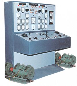
* Control Panel :
* 230 V Mains M.C.B :
Two identical dual pole M.C.B’s of inductive grade are provided for 230V mains ON / OFF of rated capacity. These are properly mounted and wired for correct operation.
* 440 V Infinite Bus ( 3 Mains ) M.C.B :
One three pole M.C.B. of inductive grade is provided for 440V Infinite Bus ( 3 Mains ) ON/OFF of rated capacity. This is properly mounted and wired for correct operation.
* DC Three Point Starter :
Two identical DC three point starters for starting two separate DC shunt motors of rating 230 V, 5HP, 1500 rpm. These two starters are properly mounted and wired for correct operation.
* Regulator for DC Motor Field Winding :
Two identical rotary regulators of rated capacity are provided for controlling the field winding of the two DC motors. These two regulators are properly mounted and wired for correct operation.
* Regulator for DC Motor Armature Winding :
Two identical rotary regulators of rated capacity are provided for controlling the armature winding of the two DC motors. These two regulators are properly mounted and wired for correct operation.
* Regulator for Alternator Field Winding :
Two identical rotary regulators with ON / OFF switch of rated capacity are provided for controlling the field winding of the two alternators. These two regulators with ON / OFF switch are properly mounted and wired for correct operation.
* Selector Switch :
A selector switch is provided to select either an alternator or infinite line bus ( 3 f mains ).
* Supply Bus :
Supply wiring with connectors to both DC machines and DC excitation of alternator is provided. Also the AC and DC bus bars with proper heavy current terminals for connections are provided. These are properly mounted with isolators and wired for correct operation. Proper colour coding is done for correct identification.
* Contactors :
Various contactors with necessary wirings and ON / OFF push button switches are provided for the following :
1. Output of alternators to panel.
2. Output of one alternator to bus.
3. Output of 2nd alternator to bus ( synchronizing ).
4. Output from bus to load.
* Indicators :
|
|||||||||||||||||||||||||||||||||||||||||||||||||||||||||||||||||||||||||||||||||||||||||||||||


Connect with us