Listing ID #6773356
Company Information
Ask for more detail from the seller
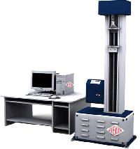
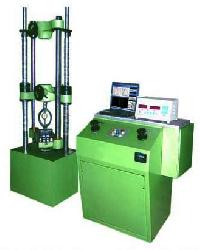
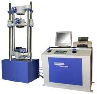
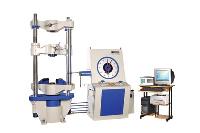
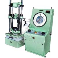
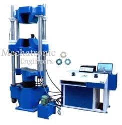
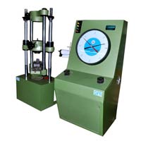
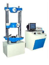
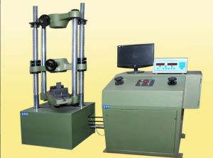
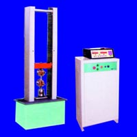
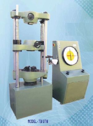
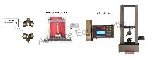
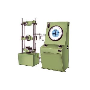
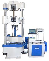
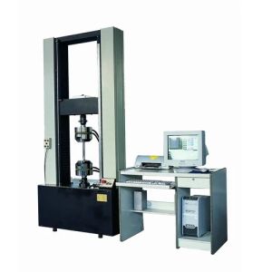
Contact SupplierApplications Mechatronic Engineers make Universal Testing Machine is designed for testing metals and other materials under tension, compression bending, transverse and shear loads. Hardness test on metals can also be conducted Accuracy & Calibration All Mechatronic Engineers make Universal Testing Machines are closely controlled for sensitivity, accuracy, and calibration during every stage of manufacture. Every Machine is then calibrated over each of its measuring ranges in accordance with the procedure laid down in British Standards 1610: 1964 and IS 1828-1975. Mechatronic Engineers Universal Testing Machines Comply with grade “A” of BS: 1610: 1964 and grade 1.0 of IS -1828-1975 An accuracy of + 1 % is guaranteed from 20% of the load range selected to full load. Bellow 20% of the selected range, the maximum permissible error is 0.2% of the full reading. Principle of Operation The operation of the machine is by hydraulic transmission of load from the test specimen through DIGITAL PRESSURE TRANSDUCER to a separately housed load indicator. The system is ideal since it replaces transmission of load through levers and knife edges, which are prone to wear and damage due to shock on the rupture of test pieces. The load is applied by a hydrostatically lubricated ram. Main cylinder pressure is transmitted to the DIGITAL PRESSURE TRANSDUCER housed in the control panel. The DIGITAL PRESSURE TRANSDUCER gives a signal to the DIGITAL ELECTRONIC DISPLAY UNIT corresponding to the load exerted by the main ram. Simultaneously the digital Electronic Encoder fitted on the straining unit gives the mechanical displacement to the DIGITAL ELECTRONIC DISPLAY UNIT. Both the signals are processed by Microprocessor and LOAD and DISPLACEMENT is displayed on the to DIGITAL ELECTRONIC DISPLAY UNIT Machine consists of Machine consists of Straining Unit This consists of a hydraulic cylinder motor with chain and sprocket drive and a table coupled with the ram of the hydraulic cylinder, mounted on to a robust base. The cylinder and the ram are individually lapped to eliminate friction. The upper cross-head is connected to two screwed columns which are driven by a motor. Axial loading of the ram is ensured by revealing the cylinder and ram of any possible side loading by the provision of ball seating. Tension test is conducted by gripping the test specimen between the upper and lower cross-heads, Compression, transverse, bending, shear, and hardness tests are conducted between the lower crosshead and the table. The lower cross-head can be raised or lowered rapidly by operating the screwed columns thus facilitating ease of fixing of the test specimen. Control Panel The Control Panel consists of a power pack complete with drive motor and an oil tank, control valves with to DIGITAL ELECTRONIC DISPLAY UNIT. A pressure transducer is connected for load indicator and a rotary encoder for elongation with a resolution of 0.1 mm, is provided to measure the deformation of the specimen Power Pack The power pack generates the maximum pressure of 200 kgf/cm2 the hydraulic pump provides continuously non-pulsating oil flow. Hence the load application is very smooth. Hydraulic Controls Hand operates wheels are used to control the flow to and from the hydraulic cylinder. The regulation of oil flow is infinitely variable incorporated in the hydraulic system is a regulating valve which maintains a practically constant rate of piston movement. Control by this valve allows extensometer readings to be taken. Load Deflection Indicator It is a microprocessor-based electronic control panel connected with a machine using a Pressure Transducer, Rotary Encoder, and Electronic Extensometer. Using the RS-232 serial communication port our s/w communicates with the machine and gets real-time Load, Deflection, and Extension, and shows on the computer. Electronic digital displays Load Elongation and extension. Facility to hold peak – load and tare facility to make load zero. El
| Model | ME-UTE 10 | ME-UTE 20 | ME-UTE 40 | ME-UTE 60 | ME-UTE 100 | |
|---|---|---|---|---|---|---|
| Maximum Capacity | kN | 100 | 200 | 400 | 600 | 1000 |
| Measuring Range | kN | 0-100 | 0-200 | 0-400 | 0-600 | 0-1000 |
| Load Resolution | N | 5 | 10 | 20 | 30 | 50 |
| Load Rage with Accuracy +/-1% | kN | 2 to 100 | 4 to 200 | 8 to 400 | 12 to 600 | 20 to 1000 |
| Displacement Resolution | mm | 0.1 | 0.1 | 0.1 | 0.1 | 0.1 |
| Clearance for tensile at fully descended working piston | mm | 50-700 | 50-700 | 50-700 | 50-800 | 50-850 |
| Clearance for compression test at fully descended working piston | mm | 0-700 | 0-700 | 0-700 | 0-800 | 0-850 |
| Clearance between columns | mm | 500 | 500 | 500 | 600 | 750 |
| Ram stroke | mm | 150 | 200 | 200 | 250 | 250 |
| Straining/piston speeds (at no load) | mm/min | 0-300 | 0-150 | 0-150 | 0-100 | 0-80 |
| HP | – | 1.3 | 1.3 | 2.3 | 2.5 | 3.5 |
| V | – | 400-440 | 400-440 | 400-440 | 400-440 | 400-440 |
| Æ | – | 3 | 3 | 3 | 3 | 3 |
| Weight approx. | kg | 1500 | 1500 | 2500 | 3500 | 5500 |
| DIMENSIONS | ||||||
| L X W X H (approx.) | mm | 2032 x 750 x 1960 x |
2032 x 750 x 1960 x |
2060 x 750 x 2180 x |
2065 x 750 x 2534 x |
2415 x 815 x 2900 x |
| Model | ME-UTE 10 | ME-UTE 20 | ME-UTE 40 | ME-UTE 60 | ME-UTE 100 | |
|---|---|---|---|---|---|---|
| FOR TENSION TEST | ||||||
| Clamping jaws for RoundSpecimens of Diameter | mm | 10-20 20-30 |
10-20 20-30 |
10-25 25-40 |
10-25 25-40 |
10-25 25-45 |
| Clamping jaws for Flat Specimens of Thickness Width |
mm | 00-10 10-20 50 |
00-10 10-20 50 |
00-15 15-30 65 |
00-15 15-30 70 |
0-22 22-44 70 |
| FOR COMPRESSION TEST | ||||||
| Pair of Compression Plates of Diameter | mm | 120 | 120 | 120 | 120 | 160 |
| FOR TRANSVERSE TEST | ||||||
| Table with adjustable rollers width of rollers | mm | 160 | 160 | 160 | 160 | 160 |
| Diameter of rollers | mm | 30 | 30 | 30 | 50 | 50 |
| Maximum clearance between supports | mm | 500 | 500 | 500 | 600 | 800 |
| Radius of punch tops | mm | 6,12 | 6,12 | 12, 16 | 16, 22 | 16, 22 |

Connect with us