Company Information
Ask for more detail from the seller
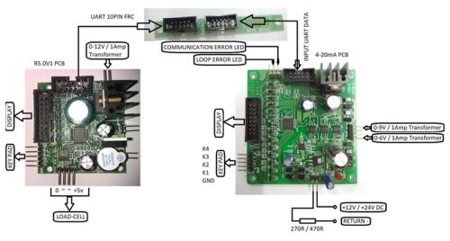
Contact SupplierThe I-SYS 4-20mA loop transmitter PCB is user configurable. User configurable setpoint1 &setpoint2 values can be entered into the controller using the keypad & seven segment display.The controller will deliver linear current output from setpoint1 load value (4mA) to setpoint 2 load value (20mA). Make sure that the setpoint2 value is greater than setpoint1 value. The 4- 20mA loop transmitter (DAC) PCB receives weight data from R5.0v1 weighing scale PCB as serial UART data. The DAC PCB can be configured to 2400 or 9600 bauds in 8N1 format. The data output speed from R5.0V1 PCB is 10 data samples per second. During normal operation, the display connected to the DAC PCB will show the serial weight data received from the R5.0V1 PCB. During a fault condition, the DAC PCB may report any of the two types of error. The loop error led will be lit when the current loop is open. To reset this error indication, press key K4. The communication error LED will be lit when no communication or UART DATA is received by the loop controller to update the DAC IC. This LED will automatically be reset upon reception of UART DATA.
To configure the machine, connect the power supply. Now press key (K4) and with the key (K4) pressed power on the DAC PCB. Make sure that the weighing PCB (R5.0V1) is already powered up and transmitting the UART DATA. The default baud rate of the weighing PCB supplied with the DAC PCB is 9600 BPS.
It shows
| P | A | R | A |
Now press key (K1) to go to parameters PARA (Parameter) settings.
| S | E | T | - | 1 |
It will display “SEt-1” briefly and then show as below…
| 0 | 0 | 0. | 0 | 0 | 0 |
The decimal point will be automatically placed at the right range/position based on the serial weight data received from the R5.0V1 PCB. Enter the setpoint1 value by pressing the increment key (K2) and the shift key (K3). After setting the right value press the enter key (K1) for the value to be stored in the controller’s permanent memory.
| S | E | T | - | 2 |
Next, it will display “Set-2” briefly and provide space to enter setpoint2 value…
| X | X | X. | X | X | X |
Enter the setpoint2 value & press key (K1) to store the value in memory.
Next, it will show…
| B | A | U | D | 0 |
Use key (K2) to change the value.
BAUD – 0 FOR 9600 BPS DEFAULT
BAUD – 1 FOR 2400 BPS
Press the key (K1) to store the value in memory.
Next, it will show….
| P | S | 0 |
PS stands for power save in 7-segment weight display.
PS – 0 MEANS POWER SAVE FUNCTION IS ACTIVE.
PS – 1 MEANS POWER SAVE FUNCTION NOT ACTIVE.
This function has no effect on DAC performance & can just be ignored.
Press key (K1) to store the value in memory.
It will once again display…
| P | A | R | A |
Your configuration is complete. You can now switch OFF & ON the DAC PCB power supply.
Your loop current transmitter is now ready for use.

Connect with us