Listing ID #4235178
Company Information
Ask for more detail from the seller
Contact SupplierSolar Power OperationThere is DC high cutoff (battery fully charged) and DC Low regain (Buffer backup voltage) points in Solar PCU. Once Solar PCU is with PWM/MPPT Charge controller PWM/MPPT CC), will Charge batteries simultaneously along with Grid Charger. At this time load will be on grid. Once battery voltage reaches grid charger cut off preset voltage then grid charger stops charging. Now PWM/MPPT CC will charge batteries through Solar power. Load will be on grid. (Preset value as per customer requirement). When battery voltage reaches DC high cutoff voltage (Battery is fully charged). Then Solar PCU disconnects grid supply and Load is transferred to Inverter in 4ms. Now Solar gives power to inverter and for battery charging. Solar PCU will work through solar until solar is healthy. When solar power not sufficient PCU will take deficit power from battery. When battery voltage reaches DC Low regain (preset value as per customer requirement) (Buffer backup voltage) Solar PCU will shift load from Inverter to grid. Buffer backup is for emergency use in case of grid power failure. Now grid charger will charge battery up to buffer backup level for emergency and load will be on grid. Once Solar power is available then PWM/MPPT CC will charge the Batteries and the process continues. Solar PCU will not deep ischarge the Batteries. On PCU Operation Battery Discharge level is customer adjustable. While PCU DC Low Regain Condition ,If Grid supply is not available then battery will give power to load. If the Battery is fully discharged and tripped. Solar PCU will automatically starts its Operation Once Solar/ Grid available.
Sleep Mode
Salient Features
Applications
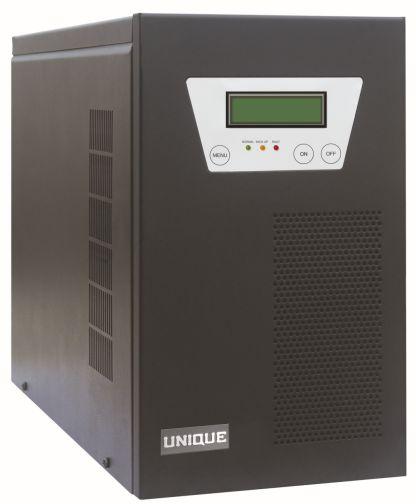
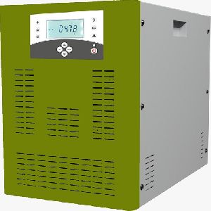
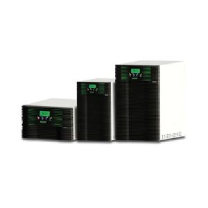
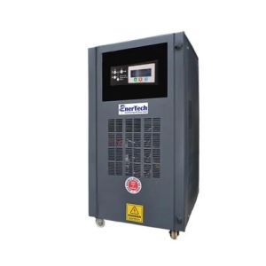
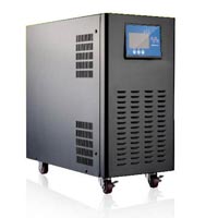
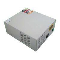
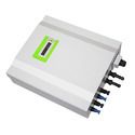
| Model | Unique Vivid Series Solar Power Conditioning Unit | |||||||
| Array rating | 1 kW | 2 kW | 3 kW | 4 kW | 5 kW | 6 kW | 4 kW | |
| Array input | 56 v to 88 v DC | 112 v to 88 v DC | 140 v to 220 v DC | |||||
| Charger Controller type | PWM MPPT | |||||||
| Battery Voltage | 48 V DC | 96 V DC | 120 V DC | |||||
| Battery Type | SMF/Lead Acid | |||||||
| max DC Charging Current | 18 A | 35 A | 52 A | 35 A | 44 A | 52 A | 52 A | |
| Inverter Type | Bi-Directional | |||||||
| Output Power Capacity | 1KVA | 2KVA | 3KVA | 4KVA | 5KVA | 6KVA | 7KVA | |
| Load Power Factor | 0.8 lag. To Unity | |||||||
| Grid Input Voltage Range | 110V-275V AC | 160V-275V AC | ||||||
| Nominal Output range | Four Steps AVR 220V+3%-17% | Same As Input Voltage | ||||||
| Regulation(inverter Mode) | +2, -5% | |||||||
| Frequency | 50 Hz (+/-0.5 Hz)in stand alone mode | |||||||
| waveform | True Sine Wave | |||||||
| Total Harmonic Distrotion | <3%max. For Linear Load | |||||||
| Overload Capacity | 125% for2 min.150% for 30 seconds | |||||||
| Inverter | MOSFET based PWM with INSTANTANEOUS SINE WAVE CONTROL | |||||||
| Duty | Continous | |||||||
| Inverter Efficeincy | >85% | |||||||
| Operating Models | Stand Alone/Grid Interactive/Offline | |||||||
| Acoustic Noise Level | <55 dba @ 1 meter | |||||||
| Service Temprature | 0 to 40˚C | |||||||
| Storage Temprature | -25 to 55˚C | |||||||
| Relative Humadity | Upto 95% (Non condensing) | |||||||
| Altitude | <1000 meter,above sea level(without derating) | |||||||
| Cooling | Forced Air | |||||||
| Clour | Black | |||||||
| cable Entry | Rear Side | |||||||
| Dimension(in mmWx Dx H) | 480*194*335 | 530*240*510 | 555*360*720 | |||||
| Approx Weight in Kg. | 25 | 32 | 55 | 60 | 68 | 82 | 124 | |
| Led Indication | Invertor On Inverter UV/OV | |||||||
| Grid ON Inverter Overload | ||||||||
| Battery Low | ||||||||
| Protection | Input Surge Voltage | MCB At output | Output Under Voltage | |||||
| Input Under Voltage | Output Over Voltage | |||||||
| Input Over Voltage | Battery Low Trip | output Overload | ||||||
| Low/High Frequency | Over Temperature | Output Short Circuit | ||||||
| *Alarms are provided for all important protaction | Load Surge Current | |||||||
| Optional features | Inverter ON/OFF Switch Array Blockin Diode | Auto Restartin case of Overload Shut Down |
||||||
| Manual Bypass Switch sleep mode with auto restart | ||||||||
| Rs 232 port for monitoring | ||||||||
| LCD DISPLAY & FAULT DISPLAY | ||||||||
| LCD Display | BatteryVoltage Battery Charge (%) Grid Frequency PV Voltage(Optional) PV Wattage(Optional) | |||||||
| Output Voltage Output Load (%) Output Frequency PV Cirrent (Optional) Generated Units (Opetional) | ||||||||
| Grid Voltage | ||||||||
| Fault Display on LED | Ouput Under Voltage Output Over Voltage Inverter Overload | |||||||
| Battery Low Pre Alarm Battery Low Trip | ||||||||

Connect with us