Our Products
Our offered Product range includes A.C. HIGH VOLTAGE BREAKDOWN TEST SET, Auto Synchroniser, Load Managers, SINGLE PHASE SMART ANALYSER C 80 and Leica Disto Classic.

Applications
Rugged Construction
Confirms to:
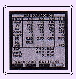
Display features
| Power Max EM 6434 | Power Max EM 6400 |
| All EM 6434 features Plus
|

Product Description : UP
| Smart Features: |
|
| Applications: |
|

Displays
Smart Features:
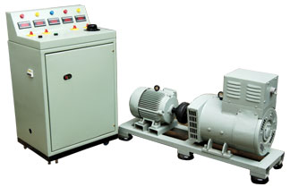
| Operations: |
| Frequency balancing: The instrument has two output relays which compare the frequency difference between electric mains and generator mains. If the difference is more than 5 Hz, the instrument gives output impulses in the right direction (slower or faster) to the speed governor of the Genset to achieve frequency balance. Voltage balancing: The relay has built-in voltage comparator which measures and compares the voltage difference between electric mains and generator mains. When it finds voltage equal or within set limit, the front voltage V LED glows. Phase shift balancing: To determine phase accordance between the generator and the electric mains, the SyncroMax will calculate a phase angle at the instant of frequency balance based on the set circuit breaker closing time. If this phase angle is within the set limits, the SyncroMax transmits a closing signal for the generator circuit breaker and indicates Synchronisation. |