Our Products
Welding Machines & Equipment
2 Products availableSheet Metal Machinery
2 Products availableWelding Machine Parts
2 Products availableNuts Bolts And Fasteners
1 Products availableWire Making Machines
1 Products availableIndustrial Machinery
1 Products availableElectric Cable Making Machine
1 Products availableWe offer a complete product range of Spot Welding Machine, flash butt welders, Seam Welder for Steel Mill, Side Seam Welders and Brake Shoe Welding Machine


These machines are robust in construction and are precision-built for long trouble-free service. Each machine is submitted to rigorous proving tests before delivery, so that the machine is ready for immediate installation and operation at the customer's works.
The Know-How that enables MECHALONIC ENGINEERS to offer these machines is backed by many years of experience in Welding Technology.
These Flash Butt Welders are specially designed for heavy duty applications where repeatability in performance is very important. Tooling and clamping devices are available for adapting these machines for the manufacture of railway shackles, automotive parts, starter ring-gears, wheel rims, link chains, etc.
For accurate and consistent weld results fully solid-state electronic controls are provided. Semi-automatic and fully automatic modes of operations are possible. Machine incorporating PLC and SERVO System are also available on request.
These machines conform to the latest National / International Standards.
Specifications:
Standard Ratings: 150, 200, 250 KVA (Higher capacities available on request).
Type of Machine FH - Series: Automatic and semi-automatic high-speed flash Butt Welding Machine with hydraulically operated clamping and upsetting mechanism.
Construction: Main frame assembly is of sturdy, all-welded steel plate fabrication suitably braced and stiffened at points of stress to minimise deflection and thermally stress-relieved; the transformer placed separately from the main frame and connected through flexible connectors. Left hand platen is fixed and right-hand platen is movable and guided on precision - hardened and ground slides with provision for wear adjustment.
Welding Transformer: Transformer is of special type conforming to IS: 4804 Part I - 1968 and TWMA Standards. Water cooled, having core of high grade electrical steel, primary and secondary coils of solid electrolytic copper of ample section, heavy duty class 'F' insulated and encapsulated and suitable for withstanding severe loading conditions. Thermostatic protection has been provided against overheating of the transformer. In case of overheating, the control circuit opens, thereby preventing its operation till normal condition is attained.
Current Control By Transformer Taps: Transformer primary coil provided with taps brought out to tap changing links for adjustment of welding current in 4 steps from 50% to 100%. Tap change links are enclosed behind the machine panel.
Cooling System: Transformer, secondary bus bars and electrodes and thyristors are water-cooled. Internal water-cooling piping is provided in the machine. All circuits terminate into a single outlet.
Water Flow Switch: (Optional accessory at extra cost). Water Flow Switch shall be provided with machine to ensure adequate flow of water while operating the machine. When sufficient flow of water is not provided the control circuit trips off and machine stops. Visual indication shall also be provided to indicate inadequate flow of water.
Clamping & Tooling: Clamping pressure applied by individual hydraulic cylinder through either alligator-type lever operated clamps or vertical clamp slides depending on job configuration.
Upper and lower tooling fitted with one set of replaceable electrodes / dies to suit particular geometry of the components.
Pre-Heat, Flashing & Upsetting:
A movement of right-hand platen is effected by a direct acting hydraulic cylinder. Provision is made for automatic pre-heating of the work pieces prior to the commencement of the flashing operation. The retractable cylinder facilitates only a small stroke of the cylinder to be operational during this period. The ON and OFF timing periods of pre-heating are separately controlled by precision electronic timer having a range of 2-250 cycles continuously adjustable. The numbers of pre-heat cycles are selected from 0-99 impulses in steps of one impulse. Flashing parameters such as the initial speed, rate of acceleration and final speed are under the control of a flow control valve. This valve determines the initial speed of flashing and acceleration and final speed achieved by the moving platen at the pre-set distance. Upsetting is achieved by bypassing the flow control valve and dumping the oil suddenly. Upsetting pressure can be varied by means of pressure regulating valve. Cutting off the current just after the application of the upset force is controlled by precision electronic timer. Welding current interrupted automatically after pre-adjusted interval starting from the moment of upsetting by an Electronic timer unit adjustable to suit any welding requirement.
Post-Heat(Optional at extra cost):
A post-heat timer and a programmable 6-second downslope control of absolute accuracy enabling excellent post-weld heat treatment to the weld heat treatment to the weld joint can be provided at extra cost.
Contractor:
Heavy-duty Thyristor Contractor incorporated in the primary circuit for on/off switching of the set. Main power contractor is chosen as per the requirement of the welding machine. Two high Power thyristors on a water-cooled heat sink are connected in anti-parallel. The gates of the thyristors are connected to the firing circuit, which triggers the firing signals to the thyristors. The thyristors are protected from voltage and current surges by conservative designs. A thermo switch mounted on the water-cooled heat sink offers additional safety to the Thyristors.
Servo Control(Optional at extra cost):
Control functions such as Pre-heat, Flashing, Upsetting and Post Heat, which are done with Non-synchronous timers and relay logic is replaced with a compact PLC with appropriate programming. The right hand side platen movement is controlled by means of a Servo Valve having position feed back (with the help of Linear Transducer) and current feedback for proper flashing and upsetting. Pressure feed back is also applied to the Servo system during pre-heating for fast and controlled heating. Flashing parameters such as initial speed, rate of acceleration, flashing speed, etc. are controlled with the help of servo valve to get optimum results.
Hydraulic Power Pack: The hydraulic power pack is an integral unit, consisting of a tank, strainer, pumping unit, heat exchanger and the group of valves and devices as per the circuit of the system arranged for easy servicing. Only the hoses are to be connected to the bulk heads provided for starting up the hydraulic system. It is powered by a 3-Phase Induction Motor.
Service Requirements
Supply Voltage:
415 Volts, Single Phase, 50 Hz. (2 lines of 3-phase supply) for transformer. 415 Volts, 3-Phase. 50 cycles, for hydraulic power pack as given in technical specification.
Main Supply Disconnect Switch:
To be provided by customer. 2-Pole, Isolating Switch Unit (rating as recommended).
And 3-Pole, Isolating Switch Unit (rating as recommended). Mains Supply Cable: To be provided by customer, 2-Core, copper/aluminium conductor (rating as recommended). And 3-Core, Copper / aluminium conductor (rating as recommended).
Water: Customer to provide water supply of recommended flow rate, free from residue forming impurities and at a temperature less than 30oC.

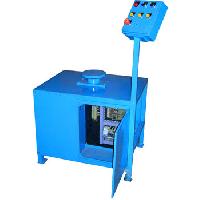
Seam Welder for Steel Mill
This special purpose moving head seam welder is specially designed for steel strip joining in continuous processing plants such as galvanizing plants, coating plants and rolling mills. This machine is primarily used for high speed operation providing minimum pause in line for coil joining. The high strength limited overlap joint produced in the strip is quick and economical for processing.
Construction:The main frame of the machine consists of a fabricated bridge structure with adequate reinforcement to provide rigidity. The upper beams support and guide the welding head trolley. The lower part supports the shunt and takes up the welding force besides supporting the clamps and other accessories. This designs combines a compact streamlined appearance with maximum resistance to mechanical deflection.
The welding head consists of two weld wheel holders with silver contacts, independently mounted on individual guided rams. One of the weld wheels is used for welding, whilst the other is used for the return path. The independent mounting ensures that the requisite welding force can be applied to the weld wheel and the return path wheel. The welding transformer along with the welding head is trolley mounted. His ensures the same electrical path throughout the width of the strip being joined.
A variable drive is provided to the trolley to achieve the welding speed. The is suspended from a track on the top part of machine frame. A rigid beam at the bottom provides support for the backup for the strips at the bottom.
The strips are clamped along the full width a cylinder at either end to provide uniform clamping force. The clamps retract to provide clear passage for the strip.
Control:The sequence control of the machine is through a PLC. The welding current control is through a thyristor contactor. This in turn is controlled by a thyristor firing circuit housed in an independent rack inside the control cabinet. The welding speed control is also provided away from the operator control panel (since there is a tendency to disturb setting and hence the weld quality). The operator station has facility to vary the weelding current. The heat-cool is provided inside the control cabinet. The thyristor requires water cooling and is protected by water flow switch, thermoswitch, thyrectors etc.
Optional Accessories (At extra cost)
Re-squaring Shear:An integral hydraulically operated shear at entry end trims the tail end of the coli prior to welding.
Tail-end Positioner:After trimming the tail end, the strip is positioned automatically to ensure the required overlap for welding and clamped. This facility can only be used in conjunction with resquaring shear.
Weld Identification Hole Punch:A punched hole for weld identification is provided( usually dia. 25mm).
Notcher (Optional):
A notcher is provided on either side of the sheet. This is used to provide a notch at either end of the joint when sheets of different widths are joined to enable smooth entry of a wider head end of a new coil or to enable setting of slitter on a narrower head end of new coil. The notcher shall be capable of notching a joint where the difference is width of the two sheets to be joined shall be 150 mm at each notcher. Edge sensors are provided to automatically position the notcher with respect to the sheet edge when initited. This shall be used alongwith the puller for precise positioning of joint in centre of notcher when required.
Four Point Centring (Optional):
The four point centring mechanism consists of two sets of vertical rollers mounted on LH and RH lead screws on positioning drive shaft. These rollers also have edge sensors which determine the position of each roller with respect to the sheet edge. When all the sensors (or any three) sense the sheet, the sheet will have been centered. This set of centring rollers are required one each on the head end side and tail end side of the welding position for the two sheets to be joined.
Inerlock with Line Computer (Optional):
Facility for interlock with line computer is provided by suitable interfacing of hardware and software interlocks.

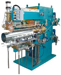
MECHELONIC ENGINEERS Container Side Seam Welding Machine model 18-51 is a trustworthy and economic way of producing consistent, faultless and narrow weld at highest working speeds eliminating need of skilled operator.
Weldability:The machine is capable of welding a wide range of materials, Tin sheets, Black and TFS sheets (after proper edge cleaning) with thickness ranging from 0.2 to 0.4 mm and body diameters ranging from 52 to 300 mm and body height upto 450 mm depending on the lower arm size.
Intermediate Electrode:Use of electrolytic copper wire as an intermediate electrode between weld wheel and tin sheet, avoids deposition of molten tin on weld wheels and ensures consistent, quality weld without frequent cleaning of wheels.
Welding Arms:Upper arm made out of high tensile brass is common for complete range of can diameters and is actuated by a hydropneumatic-damping cylinder to avoid initial impact on contact with lower weld wheel and to maintain constant welding force. Lower arm is complete with carriage guide rail, Z-bar, weld wheel etc. Three standard sizes of lower arms are available. Any one size of arm will be provided with machine, other sizes will be available at extra cost.
Weld whels & Z-bars:Antifriction, mercury contact weld wheels made out of special copper alloy & Z-bars made out of wear resistant material are available in three standard sizes i.e. 52, 65 and 100 size suitable for respective arms. These wears out parts are available as spares off the shelf. Standard overlap provided on Z-bar is 4 mm.
Carriage:Carriage assembly with built-in pneumatic clamping and limit switches for low/high current initiation, auto cut off and frame contract is mounted on antifriction bearings and can be adjusted for different can lengths easily. Different sizes of carriages are available to match each size of arm. Movement of carriage is actuated by automatic fly-start system to maintain normal welding speed from the start.
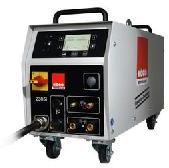
Electronic Control:
High precision fully solid state welder control incorporating thyristors permits uniform weld quality. Two-stage heat control unit controls the intensity of weld current at the beginning of weld cycle at desired low levels. Current control is through transformer taps and potentiometers.
Operation and work cycle:
Once the welding parameters like current, pressure, speed, carriage positioning, high /low heat and cut-off limit switch setting is over, operator must feed a pre-rolled sheet into the carriage and Z-bar, pushing it lightly against frame contact actuators.
On actuation of frame contact limit switches all further operations take place automatically.
Rolled body is clamped at the rear with pneumatic clamps.Upper welding roller comes down making contract with lower weld wheel and welding pressure is developed between wheels by hydropneumatic clamping cylinder and spring.Once the correct welding force is generated, the switch fitted on cylinder actuates wire feed system.The carriage is pushed forward at the start of operation by means of fly-start mechanism.Initially reduced current is applied for a pre-determined length and thereafter-full welding current is provided. The weld initiation with reduced current and change over to full current is done automatically by welder control.At the end of weld, the current is cut-off, wire, feed system stops and upper weld wheel goes up automatically.The job can be taken out after clamps are released and carriage is pulled back by spring balancer making machine ready for next cycle.Provision is also made for foot switch initiation in place of frame contact to initiate weld cycle.
Easy Maintenance:Open side mounting of weld wheels, with easy accessibility to every working part along with use of highly reliable, high quality parts like solenoid valves, bearing, weld wheels, etc. reduce the need and frequency of maintenance.
A class 'F' insulated welding transformer and other specially built assemblies like drive unit, wire reservoir, control system allow 24 hour continuous operation of machine.
Service Facilities: (to be provided by customer)
Compresses Air:Minimum pressure 5.6 Kg./cm sq.
Cooling Water:
10 LPM @ 3 kg/cm sq. pressure and 18 degrees C for welding arm cooling. 10 LPM @ 3 kg/cm sq. pressure and 30 degrees C for thyristor cooling

| Brake Shoe Welding Machine This special purpose projection Welding Machine is specially designed for welding brake shoe assemblies. The machine is equipped with basic welding Transformer, Microprocessor based control, pneumatically actuated vertical welding head and special rotary indexing fixture with drives etc. The general layout of the machine is as shown in figure enclosed. Operation:The web is located on the rotating fixture and the rim is placed correctly locating its relative position with respect to the web. The welding is initiated by foot-switch. The weld schedule is executed and the fixture automatically indexes to the next projection. In case foot-press continues to be pressed, the weld schedule is repeated. This continues as long as the foot-switch depressed. Each rotary table carries two fixtures. Hence one fixture is free for loading/ unloading when the other is being welded. It is feasible for the operator to keep the machine in continues operation whilst loading/unloading the fixtures(electrodes) sequentially. The OFF TIME setting in the weld schedule can be used to control the cycle time without hampering weld quality and to suit operator convenience. Constuction:The main frame of machine is of heavy, rigidly reinforced welded steel construction. It combines a compact streamlined appearance with maximum resistance to mechanical deflection. The transformer is housed inside the machine frame. The drive system comprising of the motor, reduction gear box, and clutch brake are mounted on the base of the machine and connected to the rotary indexing table. The fixture assemblies also carry the indexing cams preset for the specific component and hence no setting is required each change of job. Welding Transformer:Transformer of a special type, conforming to IS: 4804, Part I 1968, is used. It is water cooled, with core of high grade copper are of ample section. The secondary is of special hollow section for efficient water cooling. Heavy duty class F insulation is used. A thermo-switch mounted on the secondary trips the control circuit in case of temperature rise above preset value to protect transformer fro overheating. Current Conrol by Transformer Taps:The tap change link incorporated with the transformer provides a choice of 4 secondary voltages nd current values thereby allowing an adjustment of welding current from 50% to 100%. Tap change links are accessed from machine rear door. Weldor Control:Microprocessor based welder control, generally as per specification attached, complete with thyristor contactor is provided. Cooling Systems: The transformer, electrodes and thyristors are water cooled and discharge to an open drain pot for visual observation of flow. Electrode Control System: Vertical electrodes are actuated by a heavy duty adjustable stroke pneumatic cylinder. The cylinder is operated by a solenoid valve by the weld control. Compressed air at 2 kg/sqcm to 7 kg/sqcm acting through the pneumatic cylinder provides the electrodes force. Machine is provided with air filters, regulators with guage, lubricators etc. together with internal air connections. Adjustment of Weldign Force: The welding force is adjusted by setting the air pressure with the help of regulator. Forge function is also settable by proper selection of the parameters in the control. |
| Note: As efforts are constantly being made to improve both design and methods of manufacture, machine supplied may differ in details from illustrations and specification given. |

| Mechelonic Engineers Steel Grating Welding machines has been specially designed for the manufacture of steel gratings by electrical resistance welding. The application on high current and high forging pressure under precise control of a special welding controller and a PLC based sequence controller results in high quality electro forged weld joints that meet the highest standards. the machine can be used for the manufacture of world class gratings using round., square or twisted cross bars. The machine operation does not require any skilled labour. Apart from the loading of the cross and bearing bars, the machine is completely automatic. The machine comprises of hydraulically operated weld press with cross bar guides and a chain conveyor system. The welding transformers and the secondary systems are designed to ensure high efficiency. The welding parameters are easily settable through a user friendly interface to the control system. The gratings produced on the machine iffer the following advantagesHigh mechanical strength of jointHigh load bearing capacityMinimum distortionHigh dimentional accuracyNo pre-notching of bearing barClean joints |


| These machines are precision built, with careful design and robust contruction, suitable for long trouble free service. Each machine is submitted to rigorous proving tests before delivery is made, in order that the machine may be ready for immediate installation and operations at customer's works. The Know-How that enables MECHALONIC ENGINEERS to offer these machines is backed by many years of experience in Welding Technology. Machines covered under this section are single phase AC for seam welding application in the manufacture of Drums & Barrels, Fuel Tank, silencer, Muffler, Shock Absorber, etc. SPMs AND THREE PHASE D.C. MACHINES : Mechelonic Engineers have in their range a number of SPMs for seam welding applications for jobs, such as fully automatic barrel and shell welding (longitudinal), tub cover welding (circumferential), shock absorber welding, fuel tank welding and other automobile components. Mechelonic Engineers also have seam-welding machine with 3-phase DC transformer and matching controls. Specifications : Ratings KVA: 50, 75, 100 150, 200. Construction: Robust construction, streamlined appearance with maximum resistance to deflection. Welding transformer enclosed in the main frame, pneumatic control mounted on the machine. Welding Transformer: Transformer conforms to IS:4804 Part-I and RWMA Standards, water cooled, class 'F' insulation with thermoswitch protection for overloading. Current Control: Welding current adjustable from 50 to 100% by means of a tap change links. Cooling System: Thyristors, Transformer, Secondary connections and electrode wheels are water cooled. Electrode Force: Upper arm is actuated by heavy-duty 2-way pneumatic cylinder, controlled by solenoid valve. Compressed air at 2.0 Kg/cm.sq. to 5.6 kg/cm.sq. provides electrode force. Air filter, lubricator, regulator, pressure gauge are provided as standard accessories. Electrode Drive: Machines are provided with different drive system depending on the application. Customer to specify the preferred system. |
| Narrow Track Seam Welding (Optional at Additional Cost): In order to weld coated sheets for application like fuel tank, machine with narrow track welding (2.5 to 3 mm weld width) facility could also be supplied. In narrow track seam welding, weld wheels are of thickness 6 mm constantly coined for circular profile, which results in narrow contact with very high-pressure density. Due to this high-pressure density the coated material on the sheet metal is squeezed out during the welding. Motor Drive: Machine will be supplied with drive system comprising AC squirrel cage induction motor, with variable speed AC drive and Reduction GearBox as standard. |