Our Product / Services

Highlighted Features Front Open Type Cross Head Hydraulic Wedge Action Grips Fully Customized Advance Software Long test stroke and dual test space Loading accuracy as high as + 1% Straining at variable speeds to suit a wide range of materials Motor-driven threaded columns for quick effortless adjustment of lower cross-head-to facilitate rapid fixing of the test specimen. Simplicity in reading because of digital readouts Easy change from plain to threaded and screwed specimens. Large effective clearance between columns enables testing of standards specimens as well as structures. Simple controls for ease of operation Robust straining frame of an extremely rigid construction Safe operation ensured by means of safety devices. Fully enclosed and protected pressure transducer RS 232 serial port to transfer data to a computer for analysis/storage evaluation etc. Manual control & release valve operation Machine Capacity: 100 kN, 200 kN, 400 kN, 600 kN, 1000 kN, 1200 kN, 1500 kN, and 2000 kN Servo Controlled Models are Available Applications Mechatronic Engineers make Universal Testing Machine Model range ME-FE-UTE is designed for testing metals and other materials under Tension, Compression, Bending, Re-Bending, Transverse and Shear Tests. A hardness test on metals can also be conducted. This Special model is designed as Front Open Crosshead for easy Specimen changing with Wedge Action Hydraulic Grips Accuracy & Calibration All Mechatronic Engineers make Universal Testing Machines that are closely controlled for sensitivity, accuracy, and calibration during every stage of manufacture. Every Machine is then calibrated over each of its measuring ranges in accordance with the procedure laid down in British Standards BS-1610:Part1:1992 and IS-1828:Part1:1991. Mechatronic Engineers Universal Testing Machines Comply with grade “A” of BS-1610:Part1:1992 and grade IS-1828:Part1:1991 An accuracy of + 1 % is guaranteed from 20% of the load range selected to full load. Bellow 20% of the selected range, the maximum permissible error is 0.2% of the full reading. Principle of Operation Operation of the machine is by hydraulic transmission of load from the test specimen through DIGITAL PRESSURE TRANSDUCER to a separately housed load indicator. The system is ideal since it replaces transmission of load through levers and knife edges, which are prone to wear and damage due to shock on the rupture of test pieces. Load is applied by a hydrostatically lubricated ram. Main cylinder pressure is transmitted to the DIGITAL PRESSURE TRANSDUCER housed in the control panel. The DIGITAL PRESSURE TRANSDUCER gives signal to DIGITAL ELECTRONIC DISPLAY UNIT corresponding to the load exerted by the main ram. Simultaneously the digital Electronic Encoder fitted on the straining unit gives the mechanical displacement to the DIGITAL ELECTRONIC DISPLAY UNIT. Both the signals are processed by Microprocessor and LOAD and DISPLACEMENT is displayed on the to DIGITAL ELECTRONIC DISPLAY UNIT Machine consists of Straining Unit This consists of a hydraulic cylinder motor with chain and sprocket drive and a table coupled with the ram of the hydraulic cylinder, mounted on to a robust base. The cylinder and the ram are individually lapped to eliminate friction. The upper cross-head is connected to two screwed columns which are driven by a motor. Axial loading of the ram is ensured be reveling the cylinder and ram of any possible side loading by the provision of ball seating. Tension test is conducted by gripping the test specimen between the upper and lower cross-heads, Compression, transverse, bending, shear, and hardness tests are conducted between the lower cross head and the table. The lower cross-head can be raised or lowered rapidly by operating the screwed columns thus facilitating ease of fixing of the test specimen Control Panel The Control Panel consists of a power pack complete with drive motor and an oil tank, control valves with to DIGITAL ELECTRONI
Technical Details
| Model | ME-FH-UTE 120 | ME-FH-UTE 150 | ME-FH-UTE 200 | |
|---|---|---|---|---|
| Maximum Capacity | kN | 1200 | 1500 | 2000 |
| Measuring Range | kN | 0-1200 | 0-1500 | 0-2000 |
| Load Resolution | N | 60 | 75 | 100 |
| Load Rage with Accuracy +/-1% | kN | 24-1200 | 30-1500 | 40-2000 |
| Displacement Resolution | mm | 0.1 | 0.1 | 0.1 |
| Clearance for tensile at fully descended working piston | mm | 50-850 | 50-850 | 50-900 |
| Clearance for compression test at fully descended working piston | mm | 0-850 | 0-850 | 0-900 |
| Clearance between columns | mm | 850 | 850 | 900 |
| Ram stroke | mm | 250 | 250 | 300 |
| Straining/piston speeds (at no load) | mm/min | 0-65 | 0-50 | 0-45 |
| Power HP | – | 4.5 | 6 | 7 |
| Voltage | – | 400-440 | 400-440 | 400-440 |
| Phase | – | 3 | 3 | 3 |
STANDARD ACCESSORIES
| Model | ME-FH-UTE 120 | ME-FH-UTE 150 | ME-FH-UTE 200 | |
|---|---|---|---|---|
| FOR TENSION TEST | ||||
| Clamping jaws for Round Specimens of Diameter | mm | 10-25 25-45 45-70 |
10-25 25-45 45-70 |
20-40 40-60 60-80 |
| Clamping jaws for Flat Specimens of Thickness Width |
mm | 00-22 22-44 44-65 70 |
00-22 22-44 44-65 70 |
00-22 22-44 44-70 90 |
| FOR COMPRESSION TEST | ||||
| Pair of compression plates of diameter | mm | 160 | 160 | 225 |
| FOR TRANSVERSE TEST | ||||
| Table with adjustable rollers width of rollers | mm | 160 | 160 | 200 |
| Diameter of rollers | mm | 50 | 50 | 70 |
| Maximum clearance between supports | mm | 800 | 800 | 900 |
| Radius of punch tops | mm | 16, 22 | 16, 22 | 16, 22 |

APPLICATION & OPERATIONS
This machine is used to test the fatigue strength of materials and to draw an S-N diagram by the research institute, laboratories, material manufacturers, and various industries. This is a rotating beam type machine in which load is applied in a reversed bending fashion. The standard 8 mm dia specimen is held in special holders at its ends and located such that it experiences a uniform bending moment. The specimen is rotated at 4200 rpm by a motor. A complete cycle of reversed stresses in all fibers of the specimen is produced during each revolution.
The bending moment is applied with the lever system and can be easily changed by moving a weight over the lever. Total number of revolutions at which the specimen fails is recorded by a mechanical counter. An interlocking system puts off the motor at specimen failure. The machine meets the requirement of IS 5075-1969.
Features


Extensometer is essential to measure the elongation of the test specimen under load, to have its mechanical properties. Mechatronic Engineers’ Extensometer Model ME-EM 1 is intended to serve the above purpose.

Mechatronic Engineers offers electronic extensometer ME-EE 2 to measure material extension with a resolution of one micron. Strain gauge type extensometer is used up to the elastic limit to determine important parameters like 0.1%, 0.2% proof stress, and Young’s Modulus. This requires Mechatronic Engineer’s make Electronic Control Panel.
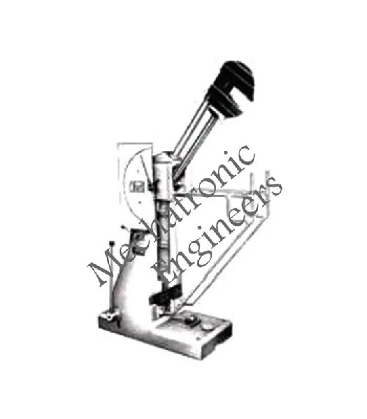
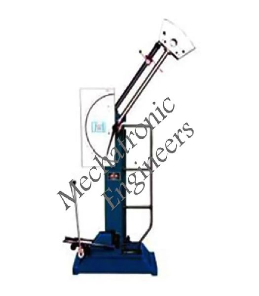
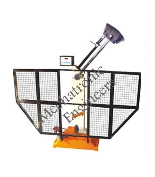
The pendulum Impact Tester of all the above models are designed for conducting Izod, Charpy test. The test methods confirm to BS : 131 : part 4-1972 (amended 15 Aug. 1993)BSEN : 10045-2 : 1993 & ASTM : E-23-94a.
The Pendulum is mounted on antifriction bearings. It has two starting positions, the upper one for Charpy & the lower one for Izod testing. On release, the pendulum swings down to brake the specimen, and the energy absorbed in doing so is measured as the difference between the height of drop before rupture and the height of rise after rupture of the test specimen and is read from the maximum pointer position on the dial scale. (It is read on Digital Panel in case of digital models)
Controls of Pendulum:
The Pendulum supports in the starting positions are by a self-resetting latch. The release mechanism is operated by a lever. The pendulum release latch is operated only when this lever is operated
Strikers & Supports:
There are two strikers and one combined support available for lifting into the pendulum and on to the base of the machine for Izod., Charpy test, changing from one striker to another is achieved simply by fixing the new striker into its position.
CHARPY TEST:
The Charpy test piece rests on alloy support anvils, fitted on the base of the machine rigidly held in position by Allen screws. The end stopper is provided for quickly and accurately locating the test piece centrally between the supports.
IZOD TEST:
The Izod test is clamped vertically in Izod support fitted on the base of the machine. The support is provided with a machined vertical groove to suit the test piece size. The front clamp piece and the Allen screw enable clamping of the test piece at an incorrect height with the help of the Izod setting gauge supplied.
MODEL ME-ASTM-E-23
This impact tester offered with 300J energy exclusively for the Charpy test confirming to ASTM- E-23. This machine is geometrically checked in the works to the more stringent requirements of the American standard. The accuracy of the machine is then verified by PROOF TEST by testing standard test specimens supplied by the NIST, USA. All two sets of the five specimens must agree with the normal values within certain tolerance specified.
OPTIONAL ACCESSORIES
On Request Charpy 400J / 500J / 600J Capacity Or Any Other Capacity Machines Are Available
| MODEL | ME-IT30 | ME-IT30-D | ME-ASTM-E-23 |
|---|---|---|---|
| Maximum capacity | 300J/168J | 300J/170J | 300J |
| Min Scale Graduation | 2J | 0.5J | 2J |
| Overall Size (Appx) | 1.1m x 0.45m x 1.65m (H) | 1.32m x 0.45 m x 1.05m (H) | 1.4m x 0.5 m x 1.9m (H) |
| Net Weight (Appx) | 375 kg | 375 kg | 450 kg |

Mechatronic Engineers’ Long Travel Extensometer Model ME-LT is used for testing high elongation material & stranded wires

Features
Technical Details
| SPECIFICATIONS | ME-TT 6 | ME-TT 10 | ME-TT 20 |
|---|---|---|---|
| Max. Torque Capacity (Nm) | 60 | 100 | 200 |
| Torque Range (Nm) | 30, 60 | 20,50, 100 | 50, 100,200 |
| Nos. of Division on dial | 600 | 500 | 500 |
| Test speed and direction | 1.5 RPM | 1.5 RPM | 1.5 RPM |
| Clearance between grips (mm) | 0-400 | 0-400 | 0-450 |
| Grips for square bar (mm) | 1 – 5 | 3-6 | 6-9 I 9- 12 | 7- 10 | 10- 15 | 15-20 |
| Motor HP | 0.5 | 0.5 | 0.5 |