Our Products
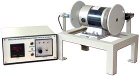
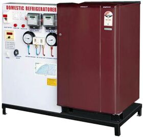
We offer a complete product range of Steam Power Plant Lab, Tilting Flume, Thermal Conductivity of Insulating Powder, Domestic Refrigerator Trainer and SPEED MEASUREMENT BY OPTICAL PICKUP


The 'J. P. T. I.' Tilting flume consists of a channel of size as in specifications. At the inlet a flow steadying section is provided so that there will be fewer disturbances at the test section. The gates provided at the upstream & downstream of the test section help to regulate the depth of flow. Depth measurements can be achieved with the help of a hook or point gauge mounted on a trolley which gives longitudinal and transverse movement. The slope of the bed can be adjusted to give positive or negative slopes. RANGE OF EXPERIMENT:-Study of open channel flow with slopeStudy of specific energy curveStudy of hydraulic jumpStudy of Nappe profiles over a sharp crested weirCalibration of sharp crested, Broad crested and ogee weirCalibration of a VenturiflumeStudy of flow under the sluice gate SPECIFICATION:-A hydraulic flume of c/s 200x300 mm & 6000 mm length with transparent window oneither sides of 1800 mm length. Sliding gates one at upstream and other at the downstream side.Screw jack for change of the slope of the flume.A Sump tank of sufficient capacity.Supply tank with waves damping arrangement.A 3 H.P. centrifugal monoblock pump.An Orifice meter with manometer to measure the discharge. Inlet/throat dimensions: 50/25 mm respectively.Trolley with point gauge for level measurement.Models supplied: Sharp crested weir (crest length 200 mm)Broad crested weirOgee weir or spillway.Venturi flume SERVICE REQUIRED:-Suitable Water supply. Suitable floor space to mount apparatus.15 amps Single Phase Electrical Connection.

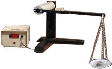
The J.P.T.I. unit consists of two thin wall concentric copper spheres. The inner sphere houses the heating coil. Heating coil is made up of nichrome wire wound on mica sheet. The insulating powder packed between two shells. Power supply to the heater is given through a dimmerstat & is measured by voltmeter & an ammeter. Temperature can be measured with the help of thermocouples. Four thermocouple are embedded on inner sphere and six thermocouples are embedded on outer sphere. The entire ten temperature indicator, these reading enable of insulating powder.
SPECIFICATION:-Radius of the inner copper sphere - ri - 50mmRadius of the outer copper sphere - ro - 100 mmVoltmeter - 0 - 300 V Ammeter - 0 - 5 ADimmerstat - 1000 wattHeater - Mica Type.Temperature indicator - 0 - 300 0CThermocouple - No. 1 to 4 on inner sphere to measure TiThermocouple - No. 5 to 10 on outer sphere to measure T0Insulating powder Asbestos magnesia commercially available powder andPacked between the two spheres.
FEATURES:-Thermal conductivity of insulating powder can be calculated.Wide range of experiments can be performed to find value over a range of temperatures.Ideal for group studies & demonstration.Panelised instruments mounted on a control panel.Easy to operate.Useful for institutions, research laboratories & insulating powder manufactures
EXPERIMENTS:-To find out the thermal conductivity of the Insulating powder packed between the two spheres.
SERVICE REQUIRED:-15 amps, Single Phase A. C. supply with earthing connection.Suitable bench area to mount the instrument.