Post Buy Requirement

Our Products

  1. Dryers 3 Products available
  2. Bio Fuels

    1 Products available
  3. Power Plant

    1 Products available
  4. Boiler And Boiler Parts

    1 Products available
  5. Machine And Precision Tools

    1 Products available
  6. Material Handling Machines & Systems

    1 Products available
  7. Wood Planks

    1 Products available

Dryers

Our product range contains a wide range of Biomass Rotary Dryer System, Biomass Dryer, Biomass Dryer System, wood chips dryer and flash dryers

Biomass Rotary Dryer System

  • Maximum size : < 40 mm
  • Maximum humidity : < 50 %
  • Biomass ouput : 1500 kg/h
  • Maximum humidity : < 15%
System Description

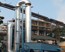
The dryer system would a conventional rotary dryer. The part of hot gas will first mix with wet material in rotary dryer .Drying would be achieved by intimate mixing of hot gas with the wet material as they travel together in the dryer drum.

The dryer would consist of the following sub-systems :

    1. Hot Gas Generator
    2. The hot gas generator consists of a furnace (solid fuel fired ), which generates hot flue gas at 800 - 1000 oC. The temperature of the flue gas is reduced to 400 oC by mixing it with fresh air after it exits the furnace system. The furnace is of refractory construction with one layer of refractory brick, followed by a layer of insulation bricks. The temperature of furnace surface would be restricted to around 100 oC only, by proper insulation. The furnace roof shall be of arch type construction for adequate strength.


      The choice of the fuel to be fired would depend on the users requirement and economics of utilisation of the fuel.


      The solid fuel furnace would have a horizontal grate for combustion of the fuel fired. The hot gas generator would be divided into two compartments, the one in which fuel would be fired and the second for completing the combustion and reducing the possibility of ash and fire particles carryover into the dryer column.


    1. Material Conveyor
    2. The material conveyor would transfer the wet biomass from the feed hopper into the dryer system. The material conveyor would be a belt conveyor of sufficient capacity. It shall be located between the hot gas generator system and the rotary dryer system.


      The belt conveyor would be driven by a 7.5 hp AC motor through reduction gear. The motor is provided with a variable speed drive so that the speed of the conveyor can be varied and the quantity of material fed into the system is controlled. Thus, if the moisture content of the wet material is much more than 40%, then the material feed may be reduced and thus the moisture content at the exit can be maintained at the desired levels, and vice versa.


    1. Rotary Dryer & Flash Dryer Columns
    2. The rotary dryer will be employed to reduce or minimize the liquid moisture content of the material it is handling by bringing it into direct contact with a heated gas. The dryer is made up of a large, rotating cylindrical tube, usually supported by steel beams. The dryer slopes slightly so that the discharge end is lower than the material feed end in order to convey the material through the dryer under gravity.


      Material to be dried enters the dryer, and as the dryer rotates, the material is lifted up by a series of internal fins lining the inner wall of the dryer. When the material gets high enough to roll back off the fins, it falls back down to the bottom of the dryer, passing through the hot gas stream as it falls. This hot gas stream can either be moving toward the discharge end from the feed end (known as co-current flow), or toward the feed end from the discharge end (known as counter-current flow). The hot gas stream is made up of a mixture of air and combustion gases.


      The wet material would be fed into the system just ahead of the dryer. Adequate spark quenching arrangements would be provided at the entry to the dryer to avoid chances of fire.


      Immediately on entering the system, due to the high temperature gradient available there would be instantaneous drying of surface moisture which would bring down the temperature of the hot gas to 200 - 250 oC. The removal of the remaining moisture would be completed in the dryer by direct heat transfer between the material and the hot gas which carries it.


      All parts of the dryer would be well insulated by mineral / glass wool type insulation for reducing the heat loss and restrict the surface temperatures to 70 oC.


      The entire system would be powered by a centrifugal blower . The blower would be belt driven by an electric motor.


    1. Electricals
    2. All electrical motors are controlled from the main panel. The feeder motor speed control shall also be from the panel. The panel would also include temperature indicators of the various drying zones. The electric motors would be provided with Star Delta starters and the remaining smaller motors shall be connected through DOL starters.


      The each RAV's shall be driven by motors through a speed reducing gear.


    1. Instrumentation
    2. The electrical panel would contain voltmeters and ammeters for the blower motor.


      The dryer system would be fitted with four thermocouples with the indicator mounted on the electrical panel. These would greatly reduce the risk of fires .


      The system shall also be provided with two pressure gages, placed before and after the blower.


    1. Supports
    2. All supports for the furnace, feeder, dryer drum etc would be from the ground. The foundation for all supports shall be provided by the client.


      The blowers with their motors would be mounted on their own concrete foundations which shall be provided by the client.


    1. Descriptive Specification Quantity
    2. The dryer is rated to produce 1500 kg/h of dried biomass with a moisture content of < 15% from an initial moisture content of 50 %.


      The rotary dryer can handle materials with a higher initial moisture content, but with a reduced output. The heat required for the dryer can be obtained from either a hot air generator, or from

      the exhaust of the gas engine or from other sources (not in scope of supply).


    1. Input raw materials specs
    2. Maximum size : < 40 mm

      Maximum humidity : < 50 %


    1. Output
    2. Biomass ouput : 1500 kg/h

    Maximum humidity : < 15%

Performance Parameters
dryer Model   RD 1500
Dry Material Output kg/h 1500
Material to be dried   Wood Chips/ Biomass
Max Input Heat kWth 1064
Hot Air Requirement at 140 Deg C m3/h 42,000
Size   powdery / granular / fibrous
Moisture content of material at inlet of the dryer   50
Moisture content of material at exit of the dryer Mg/mm3 15
Dust content in exhaust gas mg/nm3 < 600
Blower/Centrifugal Fan motor Rating hp 25
Rotary air lock motor rating hp 5
Feeder motor rating hp 3
Discharge Valve/ motor rating hp 3
Total Power consumption kw 23
Fuel consumption* @ 30 % inlet moisture kg/h 130
Fuel consumption* @ 45 % inlet moisture Kg/h 270
View Complete Details

Biomass Dryer

  • Material MS
  • Finishing Polished
  • Color Blue
  • Condition New
  • Power 5kW

The drier system is conventional pneumatic flash dryer. The hot gas carries the materials pneumatically and drying would be achieved by intimate mixing of hot gas with the wet material as they travel together in the drier columns.

The drying bin shall be filled with wet biomass to be dried from the top of the bin. The Exhaust gas from the Gas Engine shall be mixed with atmospheric air from the blower to bring its temperature down to 120 130 Deg C. The hot gas shall enter the drying bin through the inlet expansion duct, and pass through the biomass filled in the drying bin and exit the bin trough the perforated front and from the top of the drying bin. In the process, the biomass being in intimate contact with hot gas shall be dried.

After the end of the drying cycle, the drying bin would be emptied by simply opening the perforated front plate of the bin, which rests on hinges. The two bin would be operated alternately, so that one bin is working as a dryer, while the other is discharged of dried wood & loaded with fresh wood. Each batch would generate 350 -400kgs of dry biomass with 15% moisture content. The batch cycle time would be 4 hours.

The dryer would be provided with ventilation hoods to exhaust the humid air into the atmosphere via a 6 m high stack, located outside the plant building.

View Complete Details

Biomass Dryer System

Flash Dryer ( FD Series)

The Dryer system would a conventional pneumatic flash dryer. The pneumatic or flash dryer is used with products that dry rapidly owing to the easy removal of free moisture . The hot gas carries the materials pneumatically and drying would be achieved by intimate mixing of hot gas with the wet material as they travel together in the Dryer columns. Drying takes place in a matter of seconds.

Product is separated using cyclones, and /or bag filters.

The Dryer would consist of the following sub-systems :
    1. Hot Gas Generator
    2. The hot gas generator consists of a furnace (solid fuel fired ), which generates hot flue gas at 800 - 1000 oC. The temperature of the flue gas is reduced to 400 oC by mixing it with fresh air after it exits the furnace system. The furnace is of refractory construction with one layer of refractory brick, followed by a layer of insulation bricks. The temperature of furnace surface would be restricted to around 100 oC only, by proper insulation.


      The choice of the fuel to be fired would depend on the users requirement and economics of utilization of the fuel.


      The solid fuel furnace would have a horizontal grate for combustion of the fuel fired.


    1. Material( Feed ) Conveyor with Rotary Screen
    2. The material conveyor would transfer the wet biomass from the feed hopper into the dryer system. The material conveyor would be a screw conveyor of sufficient capacity. It shall be located between the hot gas generator system and the dryer system. Rotary Screen will be mounted on the top of the feed conveyor hopper to segregate oversize material & other foreign matter. The rotary screen will be driven by motor.


      The screw conveyor would be driven by a motor through reduction gear. The motor is provided with a variable frequency drive so that the speed of the screw conveyor can be varied and the quantity of material fed into the system is controlled. Thus, if the moisture content of the wet material is much more than 40%, then the material feed may be reduced and thus the moisture content at the exit can be maintained at the desired levels, and vice versa.


    1. Dryer Columns
    2. As mentioned earlier, the Dryer would be of pneumatic type. The Dryer columns would be of fabricated M.S construction. The Dryer system would consist of dryer columns of sufficient length in a single loop. The wet material would be fed into the system just ahead of the dryer.


      Immediately on entering the system, the due to the high temperature gradient available there would be instantaneous drying of surface moisture which would bring down the temperature of the hot gas to 200 - 250 oC. The removal of the remaining moisture would be completed in the dryer columns by direct heat transfer between the material and the hot gas which carries it.


      All parts of the dryer column would be well insulated by mineral / glass wool type insulation for reducing the heat loss and restrict the surface temperatures to 70 oC.


      The entire system would be powered by a centrifugal blower located immediately after the dryer columns. The blower would be belt driven by an electric motor.


    1. Dust Collection System
    2. The dust collection system would consist of high efficiency cyclone for trapping the dry biomass.


      The material collected at the cyclone bottom hopper would be removed by a two no's rotary air lock valve. This would eliminate the dust pollution at the bottom of the cyclone where the dried material would be discharged.


      The each RAV's shall be driven by motors through a speed reducing gear.


    1. Electricals
    2. All electrical motors are controlled from the main panel. The Screw feeder motor speed control shall also be from the panel. The panel would also include temperature indicators of the various drying zones. The electric motors would be provided with Star Delta starters and the remaining smaller motors shall be connected through DOL starters.


    1. Instrumentation
    2. The electrical panel would contain voltmeters and ammeters for the blower motor.


      The Dryer system would be fitted with two thermocouples with the indicator mounted on the electrical panel. These would greatly reduce the risk of fires within the column.


    1. Supports
    2. All supports for the furnace, screw feeder, dryer columns and cyclone separator would be from the ground. The foundation for all supports shall be provided by the client.


    The blowers with their motors would be mounted on their own concrete foundations which shall be provided by the client.


Salient feature of flash dryer
  • Drying is completed at low outlet drying temperatures, giving high energy utilization efficiencies.
  • High drying efficiency and low energy costs.
  • Continuous processing with short drying time.
  • Low operator overheads and minimum maintenance costs.
  • Capable of processing high capacities in a relatively small amount of space.
  • Ease of installation.
SCOPE OF SUPPLY

Biomass Dryer system

  • Conventional pneumatic flash Dryer system complete with the following :
  • Material conveying screw feeder with Rotary Screen
  • Hot Gas generator - Solid fuel fired horizontal grate furnace .
  • Dryer columns with adequate insulation
  • Dust collection system with RAV ( 2 nos)
  • Electrical motors and starters
  • Instrumentation including panel mounted temperature indicators .
  • Supports for dryer columns, screw conveyor, dust collector etc.

Terminal Points for Dryer


Power - 440 V, 3 ph at Inlet of main control panel & individual motors
Wet Biomass - Inlet to Rotary screen mounted on top of screw conveyor hopper
Dry Biomass - Exit of RAV

Design & Performance Parameters
Dryer Model   FD 750 FD 1500 FD 2500 FD 3500 FD 5000
Dry material output kg/h 550/850 1250/1750 2250/2850 3250-3850 4500/5500
Material to be dried Biomass ( Powder/Fibrous/granular)
Size < 4 mm
Moisture content of material at inlet of the dryer % < 45 %
Moisture content of material at exit of the dryer % < 12 %
Dust content in exhaust gas Mg/mm3 < 150
Blower motor Rating hp 7.5 + 3 15 + 5 25 + 7.5 30 + 10 40 + 15
Screw feeder motor rating hp 2 3 5 5 7.5
Rotary air lock motor rating hp 2 1.0 X 2 = 2 2.0 X 2 = 4 3.0 X 2 = 6 3.0 X 2 = 6
Screen hp 0.5 0.5 1 2 3
Total Connected Load hp 15 25.5 42.5 53 71.5
Actual Power consumption kw 8 14 24 29 38
Fuel For the Furnace Firewood/Briquette with 3500- 4500 kcal/kg calorific value
Fuel consumption at 30 % Initial Moisture Kg/h 60 110 150 220 300
Fuel consumption at 45 % Initial Moisture Kg/h 110 230 350 480 650
View Complete Details
Tell Us What are you looking for? Will call you back

Contact Us