Our Product / Services
Signs
2 Products availableTelecommunication Equipment & System
2 Products availableElectric Circuit Components & Parts
2 Products availableWeighing Scales & Measuring Tapes
1 Products availableElectronic Circuit Boards
1 Products availableRulers
1 Products availableSoftware Development Service
1 Services availableNetwork Interface Card
1 Products availableRelays & Contactors
1 Products availableLeading Manufacturer, Supplier & Retailer of 4-20mA Loop Transmitter PCB, RTC and USB Pen Drive Interface PCB, USB Pen Drive Data Logger PCB, RTC & Printer Interface PCB and R5.0V1 Weighing Scale PCB.

The I-SYS 4-20mA loop transmitter PCB is user configurable. User configurable setpoint1 &setpoint2 values can be entered into the controller using the keypad & seven segment display.The controller will deliver linear current output from setpoint1 load value (4mA) to setpoint 2 load value (20mA). Make sure that the setpoint2 value is greater than setpoint1 value. The 4- 20mA loop transmitter (DAC) PCB receives weight data from R5.0v1 weighing scale PCB as serial UART data. The DAC PCB can be configured to 2400 or 9600 bauds in 8N1 format. The data output speed from R5.0V1 PCB is 10 data samples per second. During normal operation, the display connected to the DAC PCB will show the serial weight data received from the R5.0V1 PCB. During a fault condition, the DAC PCB may report any of the two types of error. The loop error led will be lit when the current loop is open. To reset this error indication, press key K4. The communication error LED will be lit when no communication or UART DATA is received by the loop controller to update the DAC IC. This LED will automatically be reset upon reception of UART DATA.
To configure the machine, connect the power supply. Now press key (K4) and with the key (K4) pressed power on the DAC PCB. Make sure that the weighing PCB (R5.0V1) is already powered up and transmitting the UART DATA. The default baud rate of the weighing PCB supplied with the DAC PCB is 9600 BPS.
Technical Details
It shows
| P | A | R | A |
Now press key (K1) to go to parameters PARA (Parameter) settings.
| S | E | T | - | 1 |
It will display “SEt-1” briefly and then show as below…
| 0 | 0 | 0. | 0 | 0 | 0 |
The decimal point will be automatically placed at the right range/position based on the serial weight data received from the R5.0V1 PCB. Enter the setpoint1 value by pressing the increment key (K2) and the shift key (K3). After setting the right value press the enter key (K1) for the value to be stored in the controller’s permanent memory.
| S | E | T | - | 2 |
Next, it will display “Set-2” briefly and provide space to enter setpoint2 value…
| X | X | X. | X | X | X |
Enter the setpoint2 value & press key (K1) to store the value in memory.
Next, it will show…
| B | A | U | D | 0 |
Use key (K2) to change the value.
BAUD – 0 FOR 9600 BPS DEFAULT
BAUD – 1 FOR 2400 BPS
Press the key (K1) to store the value in memory.
Next, it will show….
| P | S | 0 |
PS stands for power save in 7-segment weight display.
PS – 0 MEANS POWER SAVE FUNCTION IS ACTIVE.
PS – 1 MEANS POWER SAVE FUNCTION NOT ACTIVE.
This function has no effect on DAC performance & can just be ignored.
Press key (K1) to store the value in memory.
It will once again display…
| P | A | R | A |
Your configuration is complete. You can now switch OFF & ON the DAC PCB power supply.
Your loop current transmitter is now ready for use.

We have a team of professionals who keep their vigil eyes on the entire lot that is stored in the warehouse. This unit keeps the lot free from the factors like duct, rain, sunlight, etc. Our assurance towards providing damage-free products to the clients is achieved through our use of quality packing material. In addition, we maintain streamlined packaging system supervised by experts.

We have high-tech in-house amenities available to make sure that the range of products we offer are kept safe till final delivery. Our team experts ensure that the warehouse is free from moisture, rainwater, sunlight, etc. Our assurance towards providing damage-free products to the clients is achieved through our use of quality packing material. In addition, we maintain streamlined packaging system supervised by experts.

The RTC & Printer Interface PCB is connected to R5.0V1 weighing scale PCB & a serial printer via an adaptor PCB using 10pin FRC cable. The Real Time Clock (RTC) PCB is connected to this board as shown in the schematic above. Make sure the +5V, ground, SCL, SDA pins are connected as per diagram. Wrong connection may damage the RTC.
The RTC & Printer Interface PCB reads the weight data (from R5.0V1 PCB) & time data (from RTC PCB) simultaneously. This time stamp is printed out on the serial printer if ENTER key(K1) on this board is pressed. This data can also be sent to a PC via RS232 interface card not shown in the diagram. Useful header data like address or slogans can be entered & stored in the EEPROM of the RTC & Printer Interface PCB. This information may also be printed along with time stamp. The customer has to enter the ascii value of the header data by looking into a ascii table. For more assistance contact the manufacturer.
Microcontrollers & RTC used
Configuring The RTC & Printer Interface PCB
To configure the PCB, connect the power supply. Now press Key(K4) and with the key(K4) pressed power on the Machine (ON-OFF switch connected to the PCB).
It shows
| t | I | n | n | E | . |
This is for setting the time in RTC Chip. Now press the Enter Key(K1). It will show
| Y | r | S | - | 1 | 5 |
This means years. Enter the year say 15 as shown…
By using Increment (INC) Key(K2) & Shift Key(K3). Press Enter Key(K1) to accept the data.
Next it will blink & show…
| n | n | o | n | 1 | 2 |
This means month. Enter value (1 to 12) using the INC Key(K2) & SHIFT Key(K3). To accept the value press ENTER Key(K1).
Next it will display day…
| d | A | Y | - | 5 |
You can enter(0 – 6). Enter “0” for Sunday, “1” for Monday & so on. Select the appropriate day value & press ENTER Key(K1).
Next it will display date
| d | A | T | - | 1 | 0 |
You can enter(1 – 31).
Next it will display hours….
| H | r | S | - | 2 | 3 |
You can enter(0 – 23).
Next it will display minutes….
| n | n | I | n | 5 | 9 |
You can enter(0 – 59)
Next it will display seconds….
| S | E | C | - | 5 | 9 |
You can enter(0 – 59)
Press ENTER Key(K1). You have successfully set the RTC clock & your clock will start running from the time you have entered.
The display returns back to time menu & will show….
| t | I | n | n | E | . |
Now Press INCREMENT Key(K2). It will show….
| C | O | n | n | . |
This means UART communication settings.
Press ENTER Key(K1). It will show….
| b | A | U | d | 0. |
You can enter values (0 – 1). Enter “0” for 9600 bauds (Default) or “1” for 2400 bauds. Press enter to accept the value.
Next it will return back to communication menu & display….
| C | O | n | n | . |
Next press INCREMENT Key(K2). It will show….
| H | E | A | d | E | r. |
This means Header data you can store in EEPROM for printing.
Press the ENTER Key(K1). It will blink & provide space for you to enter asci value.
| 0 | 6 | 5. |
Example: Enter “65” for printing character “A”. You can down load asci chart from the internet & use it to enter & print your own text data. Ascii values(0 – 127) can be entered. A total of 90 ascii characters can be stored & printed. If you want to enter only 10 characters, just enter the 10 characters one by one & then switch OFF & switch ON the PCB. There is no need to enter all the 90 characters. Value “0” is null character & nothing will be printed.

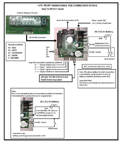
The R5.0V1 Weighing Scale PCBs are designed using advanced 16bit Renesas Microcontrollers. Our PCBs are manufactured using automatic pick & place robotic machines, bring you world class standards in performance & reliability. Our controllers incorporates high-performance selectable Digital filter Algorithm for accurate & stable measurement of weight reading. Additional Features
R5.0V1 Weighing Scale PCB User Manual-1
Weighing Scale PCB Power Supply & Battery Charging Application
Graph

We are one of the most trusted suppliers of Electronic Weigh Bridge PCBs. Our PCBs incorporates Hi-Performance Digital Filter Algorithm using Advance 16bit Renesas Microcontrollers, providing you with very high level of reliability, accuracy, stability in weight measurement. Features
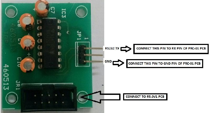
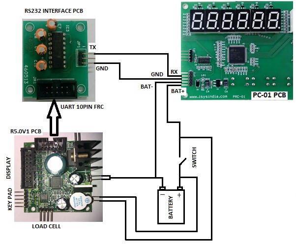
The PC-01 PCB is a 3 wire interface piece counting indicator PCB. The RS232 RX pin, GND or BAT-(battery negative pin) and BAT+ (battery positive pin) are the only 3 pins that are required for the working of this PCB.
This PCB receives RS232 weight data form R5.0V1 jewelry precision weighing scale PCB supplied to you along with it. The TTL UART signal from the R5.0V1 PCB must be level shifted to RS232 signal (via an interface PCB no.460513 also supplied to you in the kit) before connecting to PC-01 PCB.
Configuring the PC-01 : To enter configuration setup, press key1 and then power ON the PCB. The left corner display will show “PArA”. Next, Press key4 button to enter into the parameter settings. The display will show “bAU”. It means the baud rate for serial communication.
After entering the appropriate value for baud rate, press the key4 button.
After entering the appropriate value, press the key4 button. It will show “PArA” again. Press increment button key3. It will show “CAL”, meaning calibration for piece count. Make sure that PC-01 PCB is receiving serial data from R5.0V1 PCB. This is important for the calibration routine. Next press key4. It will show “ItEn”, meaning item number. Only 10 item memory is provided & their value can from 0 to 9.ITEM = 0 TO 9
Choose appropriate item number and press key4. Now the PC-01 PCB will display the received weight data. Press key4 to accept the weight data received from the R5.0V1 weighing scale. Next press key4. The display will now show all zeros. Use key3 & key2 to enter the number of pieces that were kept on the weighing machine and then press key4 to store this calibration value in controller’s memory. It will show “CAL” again. 10 different calibration values can be stored for 10 different items. The name of the items is item0 to item9. Once you have calibrated the item piece count, you can switch OFF and ON the PC-01 PCB. In the normal operation mode press the appropriate key button to change the item piece count measurement.
The PC-01 PCB displays the received weight on the 6 digit display which is at the left corner of the board. The center 5 digit display shows the unit weight of a single piece. The right 4digit (also available in 5 digits) display shows the total number of pieces measured.
Note: If you are using the reverse battery protection circuit in R5.0V1 weighing scale PCB make sure a battery is connected to the PC-01 PCB for normal functioning of PCB. Sometimes the R5.0V1 PCB will not power-up the PC-01 PCB without battery. If you still want to use the PC-01 PCB without battery, yo can do so by connecting R5.0V1 PCB in unprotected mode
PC-01 PCB has only a simple diode shorting protection for reverse battery. Hence make doubly sure to connect the right battery polarity. Wrong polarity may damage the PCB permanently & carries NO guarantee. Use of 0.5Amps fuse as protection is highly recommended.

We offer highly efficient Optically Isolated I/O Relay Card for our clients. Our Optically Isolated I/O Relay Card are very useful plug-in cards to our weighing scale board. One can easily control other electrical systems like valves, motors, etc. using our weighing scale board. Our Optically Isolated I/O Relay Card helps one to interface weighing board safely with the outside world. We offer Optically Isolated I/O Relay Card at affordable prices.

Placed in Chennai(India), ours is an emerging company serving the clients with broad range of products. We have hired proficient quality analysts having rich domain experience who make sure that only defect-free range will be delivered to buyers.
Details

The Kit contains the following items
The check weighing system provides 3-relay output for indicating 3 weighing regions. They are the low weight, normal weight & high weight. You can connect tower lamps & buzzer alarms to the appropriate relay output for visual & audio annunciation. Two set-point values are needed to be entered in the controller for creating the three zones.
Calibration of Check Weighing PCB : The calibration procedure for check weighing PCB is similar to R5.0V1 weighing scale PCB.Parameter settings in Check Weighing
Controller PCB : Please set the “PSEL” value in (“PARA”) the parameter setting to “1” to activate the set-point or check weighing functionality.
Our Check Weighing PCBs are designed using advanced industrial grade 16bit Renesas microcontrollers. They are used for accurate and fast weighing and checking of packaged commodities in a process plant and in a production line. RS232 interface to the check weighing PCB allows for data logging & printing of packing weight information. Customized programming to suit user specific relay control outputs can also be delivered.
HOW TO ENTER THE SET-POINT VALUES ?
Once the calibration & parameter setting procedure is completed, you can switch OFF & ON the Controller PCB. If no set-point value is entered in the controller, the controller will indicate “Enter Set Point” as a scrolling display. Now, press TARE key (K4) and SHIFT key (K3) simultaneously. The display will blink & then show “SET-1” for a brief period as shown below…
| S | E | T | - | 1 |
Next it shows…
| 0 | 0 | 0. | 0 | 0 | 0 |
Use the INCREMENT key (K2) & SHIFT key (K3) enter the set-point1 value. Next press the ENTER key (K4). This value will be stored in the permanent memory of the controller. Next its show “SET-2” briefly and provides you the space to enter the set-pont2 value. In a similar way enter the set-point2 value. Make sure the set-point2 value is greater than setpoint1 value.
If by chance you enter set-point2 value to be greater than set-point1 value, the controller will indicate “ERROR SET2” as a scrolling display. You will have to follow the procedure mentioned above to set the appropriate set-point values. If the set-point values are entered correctly, the appropriate relays will be switched ON or OFF as per the table shown above.
The Controller PCB also provides real time serial weight data as TTL UART output. You can use a RS232 interface adaptor for interfacing with PC. For more information regarding calibration & settings of the weighing & controller PCB, please call the manufacturer.
Weight Range
| Weight Range | Relay-1 State | Relay- 2 State | Relay-3 State |
|---|---|---|---|
| 0 to set 1 Value | ON | OFF | OFF |
| Set1 to set 2 Value | OFF | ON | OFF |
| Greater than set 2 Value | OFF | OFF | ON |
Click For More Details

Some of the salient attributes of our Coin Weighing Scale PCB that makes it highly popular among buyers are its simplicity to interface, reliability. You can get information of the amount of coins (money) collected every time the machine is switched on. You can also switch modes between normal weighing & coin weighing to easily check for accuracy of weight measurements. There is also provision for printer interface.

We offer excellent quality Jewellery Scale PCB for our valuable customers. Our Jewellery Scale PCB is extensively used in jewelley shops where high accuracy of weighing is required. Our Jewellery Scale PCB offers a precision of +-1, 35, 000 counts and 600grams/10 milli gram. Our customers can avail Jewellery Scale PCB from us at attractive prices.
Serial Communication: A 10 pin FRC box header with TTL UART Pins are available for serial communication. RS232 adaptor PCBs as shown below are available for easy interface for connecting to a PC.
The communication settings are as follow :
LED Display: 6 digit Common anode seven segment display. A 16pin FRC box connector is provided on the PCB for this purpose. Apart from segment (weight) display it will also drive a LED that indicates the presence of mains supply. Buzzer annunciation: The buzzer is used for multiple annunciations. A few are mentioned below :