New to ExportersIndia? Join Now
My ExportersIndia
For Buyer
For Seller
For Help
Our Products
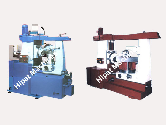
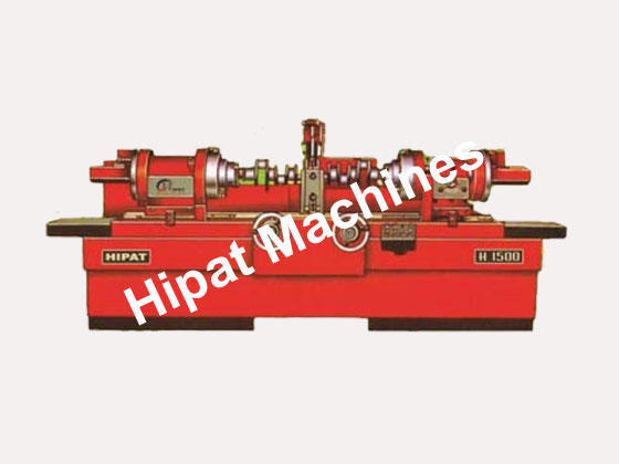
Our product range contains a wide range of Universal Gear Hobing Machine and Crank Shaft Regrinder
By clicking Send Inquiry, I accept the T&C and Privacy Policy.
Found Something Wrong with this Listing? Report Here.