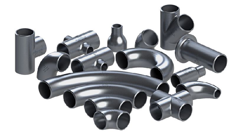
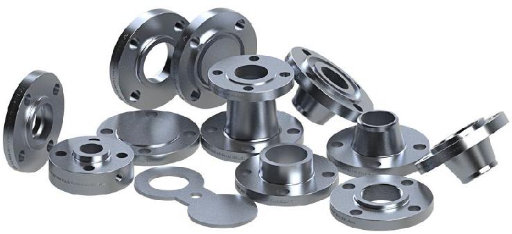
Our Products

Types :
Standards :
Features :
Notes : (For 150# & 300# Class)
Graphical Images
Dimension Of Class 600 Flanges
| NB | NPS | O | W | d | n | t | R | X | Ah | T | Y | Y | Y | B | B | B | F |
|---|---|---|---|---|---|---|---|---|---|---|---|---|---|---|---|---|---|
| S/O & S/W | W/N | L/J | S/O & S/W | W/N | L/J | ||||||||||||
| 15 | 1/2 | 95 | 66.7 | 5/8 | 4 | 14.3 | 35 | 38 | 21.3 | 16 | 22 | 52 | 22 | 22.2 | Note (2) | 22.9 | 10 |
| 20 | 3/4 | 115 | 82.6 | 3/4 | 4 | 15.9 | 43 | 48 | 26.7 | 16 | 25 | 57 | 25 | 27.7 | Note (2) | 28.2 | 11 |
| 25 | 1 | 125 | 88.9 | 3/4 | 4 | 17.5 | 51 | 54 | 33.4 | 18 | 27 | 62 | 27 | 34.5 | Note (2) | 34.9 | 13 |
| 32 | 1 1/4 | 135 | 98.4 | 3/4 | 4 | 20.7 | 64 | 64 | 42.2 | 21 | 29 | 67 | 29 | 43.2 | Note (2) | 43.7 | 14 |
| 40 | 1 1/2 | 155 | 114.3 | 7/8 | 4 | 22.3 | 73 | 70 | 48.3 | 23 | 32 | 70 | 32 | 49.5 | Note (2) | 50.0 | 16 |
| 50 | 2 | 165 | 127.0 | 3/4 | 8 | 25.4 | 92 | 84 | 60.3 | 29 | 37 | 73 | 37 | 61.9 | Note (2) | 62.5 | 17 |
| 65 | 2 1/2 | 190 | 149.2 | 7/8 | 8 | 28.6 | 105 | 100 | 73.0 | 32 | 41 | 79 | 41 | 74.6 | Note (2) | 75.4 | 19 |
| 80 | 3 | 210 | 168.3 | 7/8 | 8 | 31.8 | 127 | 117 | 88.9 | 35 | 46 | 83 | 46 | 90.7 | Note (2) | 91.4 | 21 |
| 90 | 3 1/2 | 230 | 184.2 | 1 | 8 | 35.0 | 140 | 133 | 101.6 | 40 | 49 | 86 | 49 | 103.4 | Note (2) | 104.1 | . . . |
| 100 | 4 | 275 | 215.9 | 1 | 8 | 38.1 | 157 | 152 | 114.3 | 42 | 54 | 102 | 54 | 116.1 | Note (2) | 116.8 | . . . |
| 125 | 5 | 330 | 266.7 | 1 1/8 | 8 | 44.5 | 186 | 189 | 141.3 | 48 | 60 | 114 | 60 | 143.8 | Note (2) | 144.4 | . . . |
| 150 | 6 | 355 | 292.1 | 1 1/8 | 12 | 47.7 | 216 | 222 | 168.3 | 51 | 67 | 117 | 67 | 170.7 | Note (2) | 171.4 | . . . |
| 200 | 8 | 420 | 349.2 | 1 1/4 | 12 | 55.6 | 270 | 273 | 219.1 | 58 | 76 | 133 | 76 | 221.5 | Note (2) | 222.2 | . . . |
| 250 | 10 | 510 | 431.8 | 1 3/8 | 16 | 63.5 | 324 | 343 | 273.0 | 66 | 86 | 152 | 111 | 276.2 | Note (2) | 277.4 | . . . |
| 300 | 12 | 560 | 489.0 | 1 3/8 | 20 | 66.7 | 381 | 400 | 323.8 | 70 | 92 | 156 | 117 | 327.0 | Note (2) | 328.2 | . . . |
| 350 | 14 | 605 | 527.0 | 1 1/2 | 20 | 69.9 | 413 | 432 | 355.6 | 74 | 94 | 165 | 127 | 359.2 | Note (2) | 360.2 | . . . |
| 400 | 16 | 685 | 603.2 | 1 5/8 | 20 | 76.2 | 470 | 495 | 406.4 | 78 | 106 | 178 | 140 | 410.5 | Note (2) | 411.2 | . . . |
| 450 | 18 | 745 | 654.0 | 1 3/4 | 20 | 82.6 | 533 | 546 | 457.0 | 80 | 117 | 184 | 152 | 461.8 | Note (2) | 462.3 | . . . |
| 500 | 20 | 815 | 723.9 | 1 3/4 | 24 | 88.9 | 584 | 610 | 508.0 | 83 | 127 | 190 | 165 | 513.1 | Note (2) | 514.4 | . . . |
| 600 | 24 | 940 | 838.2 | 2 | 24 | 101.6 | 692 | 718 | 610.0 | 93 | 140 | 203 | 184 | 616.0 | Note (2) | 616.0 | . . . |
Dimension Of Class 900 Flanges
| NB | NPS | O | W | d | n | t | R | X | Ah | T | Y | Y | Y | B | B | B |
|---|---|---|---|---|---|---|---|---|---|---|---|---|---|---|---|---|
| N – 2 | N – 3 | S/O & THR. | W/N | L/J | S/O & S/W | N – 4 | L/J | |||||||||
| 80 | 3 | 240 | 190.5 | 1 | 8 | 38.1 | 127 | 127 | 88.9 | 42 | 54 | 102 | 54 | 90.7 | Note (2) | 91.4 |
| 100 | 4 | 290 | 235.0 | 1 1/4 | 8 | 44.5 | 157 | 159 | 114.3 | 48 | 70 | 114 | 70 | 116.1 | Note (2) | 116.8 |
| 125 | 5 | 350 | 279.4 | 1 3/8 | 8 | 50.8 | 186 | 190 | 141.3 | 54 | 79 | 127 | 79 | 143.8 | Note (2) | 144.4 |
| 150 | 6 | 380 | 317.5 | 1 1/4 | 12 | 55.6 | 216 | 235 | 168.3 | 58 | 86 | 140 | 86 | 170.7 | Note (2) | 171.4 |
| 200 | 8 | 470 | 393.7 | 1 1/2 | 12 | 63.5 | 270 | 298 | 219.1 | 64 | 102 | 162 | 114 | 221.5 | Note (2) | 222.2 |
| 250 | 10 | 545 | 469.9 | 1 1/2 | 16 | 69.9 | 324 | 368 | 273.0 | 72 | 108 | 184 | 127 | 276.2 | Note (2) | 277.4 |
| 300 | 12 | 610 | 533.4 | 1 1/2 | 20 | 79.4 | 381 | 419 | 323.8 | 77 | 117 | 200 | 143 | 327.0 | Note (2) | 328.2 |
| 350 | 14 | 640 | 558.8 | 1 5/8 | 20 | 85.8 | 413 | 451 | 355.6 | 83 | 130 | 213 | 156 | 359.2 | Note (2) | 360.2 |
| 400 | 16 | 705 | 616.0 | 1 3/4 | 20 | 88.9 | 470 | 508 | 406.4 | 86 | 133 | 216 | 165 | 410.5 | Note (2) | 411.2 |
| 450 | 18 | 785 | 685.8 | 2 | 20 | 101.6 | 533 | 565 | 457.0 | 89 | 152 | 229 | 190 | 461.8 | Note (2) | 462.3 |
| 500 | 20 | 855 | 749.3 | 2 1/8 | 20 | 108.0 | 584 | 622 | 508.0 | 93 | 159 | 248 | 210 | 513.1 | Note (2) | 514.4 |
| 600 | 24 | 1040 | 901.7 | 2 5/8 | 20 | 139.7 | 692 | 749 | 610.0 | 102 | 203 | 292 | 267 | 616.0 | Note (2) | 616.0 |
Download

Class 150 Flanged End Connections Sure Flow Class 150 ASME Flanged strainers are available in Carbon Steel and Stainless Steel. A Machined, tapered seat ensures a perfect fit for the removable, stainless steel screen. Size 2” and larger come complete with flanged blow-off cover, gasket & plug. 1 ½” and smaller come complete with solid threaded cover and gasket. May be installed in vertical or horizontal pipelines with blow-off connection at the lower end of the screen.
ConstructionCarbon Steel : Body, Cover – ASTM A216 Grade WCB Stainless Steel : Body, Cover – ASTM A351 Grade CF8M All screens are Stainless Steel
| Standard Screens | ||
|---|---|---|
| Size | Standard | Opening |
| ½”- 1 ½” | 1/32” perf | 0.032” |
| 2” – 3” | 3/64” perf | 0.045” |
| 4” – 24” | 1/8” perf | 0.125” |
| Operating Pressures and Temperatures | |||
|---|---|---|---|
| Type | Size | psi @ Temp Steam | psi @ Temp WOG |
| YF 150 | ½”- 24” | 150 @ 358 oF | 285 @ 100 oF |
| YF150SS | ½”- 12” | 150 @ 358 oF | 275 @ 100 oF |
Download