Physical parameters:
- d (wire diameter): This parameter describes the diameter of wire used as material for spring.
- De (Larger External Diameter): External diameter at large end of the spring. Tolerance for this parameter is (+-)2%(indicative).
- Ds (Smaller Internal Diameter): Internal diameter at small end of the spring. Tolerance for this parameter is (+-)2%(indicative)
- L0 (free length): Free length of compression springs is measured in its uncompressed state after previous one time blocking. Tolerance for this parameter is (+-)2%(indicative).
- R (spring rate): This parameter determines spring’s resistance, while it is
- working. It is measured in 1 DaN/mm = 10 N/mm. Tolerance for this parameter is (+-)15%(indicative).
- P- Pitch means centre distance between two coils.
- L1 & F1 (length at force F): Force F1 at length L1 can be calculated from equation : F1 = (L0-L1) * R. Equation derrived from previous for calculating L1 : L1 = L0 – F1/R.
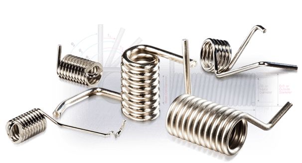
Compression springs are often specified where the large end is meant to work in a bore and the small end is meant to work over a rod. They offer the advantage of a reduced solid height compared to straight compression springs, especially when capable of “telescoping.”
Conical Springs are Cone shaped compression springs designed to provide a near constant spring rate and a solid height lower than a normal spring. Each spring features a variable pitch to achieve the constant spring rate and coils which nest during deflection to provide a solid height approximately equal to two wire diameters.
Some uses for conical compression springs are as follows:
- Small Solid Height: A Conical spring can be designed so that each active coil fits within the next coil, so the solid height can be equal to one or two thicknesses of wire. This is useful where the solid height is limited.
- Variable Rate: These springs offer a constant, or uniform pitch, and have an increasing force rate instead of a constant force rate (regular compression springs). The larger coils gradually begin to bottom as a force is applied. A variable pitch can be designed to give a uniform rate if necessary.
- Stability: Conical compression offers more lateral stability and less tendency to buckle than regular compression springs.
- Vibration: Resonance and vibration is reduced because Conical Compression springs have a uniform pitch and an increasing natural period of vibration (instead of a constant) as each coil bottoms.