Our Products
Our offered Product range includes Settable on off Long Duration Timer Circuit, Four Channel LED Running Light Circuit, Touch Sensitive Alarm, Earthquake and Vibration Alarm and Listening Bug Circuit.

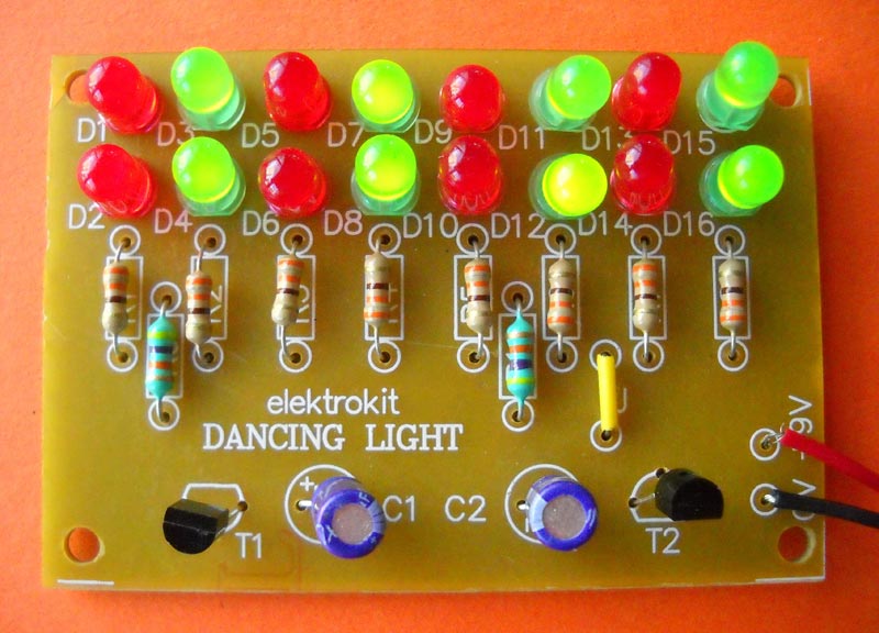
Four Channel Led Running Light Circuit is a series that exhibits LED’s flashing effect sequentially. In many applications such as model roadway, running light effects are observed. This simpleFour Channel Led Running Light consists of 16 LED’s in a pair of four. The four groups of LED are named as A, B, C, D glows simultaneously one by one. The frequency of Four Channel Led Running Light can be changed by preset P1 shown in the circuit diagram. The controlling circuit is build around decade counter, whose four outputs are used here. The circuit automatically resets when IC1 reaches to fifth count. The clock and triggering circuit are designed around five mono-stable multi vibrators in IC2.
About the Circuit :The circuit diagram of four-channel running light is shown in figure. The clock pulses generated by one of the mono-stable multi vibrator whose frequency determined by R1/P1/C1 are given to clock input terminal (pin14) of IC1. IC1 being a decade counter starts counting. The output at pin 3, 2, 4, 7 becomes logic high sequentially. When count reaches to pin10 or bit Q4, IC1 gets reset and counting starts again. The logic generated at pin 3, 2, 4, 7 of IC1 is given to four mono-stable multi vibrators in IC2. The outputs of IC2 are given to transistors as T1, T2, T3, T4, which drives four group of LED’s as A, B, C, D. Thus A, B, C, D will go on flashing sequentially. Toggle switch S1 is used as a mode selector to reverse the emitting position of LED. This effect can be view as a running light effect. Fig1 shows the combination of two LED’s in series and two LED’s in parallel configuration. And you can use number of LED’s as per your requirement in four channels. The current limitor resistor in between LED combination and collector of transistor changes the value as per the supply voltage and current consumption of LED. The value of current limitor resistor should be smaller than given in part list. Fig2 shows the sequential arrangement of LED’s. A pair of LED’s is in series in each four-channel combination. If one wants to connect more number of LED’s then, it should be connected after every fourth channel configuration as shown in fig 2, which is connected to point a after fourth channel. If number of LED’s increases, then the current limitor resistor value should be smaller than part list. This is the method to connect more number of LED’s in place one. This connection should be made properly at point A, B, C and D respectively.

Settable On Off Long Duration Timer Circuit is useful in turning air conditioner ON and OFF as per the requirement to reduce the power consumption without affecting the cooling considerably. Settable On/Off Long Duration Timer gives you adjustable ON & OFF timings from minutes to hours e.g. 4 minutes ON, 15 minutes OFF or 70 minutes ON, 10 minutes OFF. Other applications of this circuit can be household water pump ON/OFF, compressor ON/OFF in any compressed air system, blower ON/OFF in explosive gas environment.
About the circuit :The circuit is built around two CMOS 4060 IC’s both working as independently settable oscillator cum counter /divider. Pin 9 & 10 have R, C components which decides the frequency of oscillator. This oscillator frequency is fed to chain of binary counters (14) through a resistance (R1, R6). Pin 7 is the output of fourth counter. LEDs D5, D6 indicates the clock pulses. Relay driver T3 is driven by pin 3 (last counter output) of IC2.When pin 3 of IC2 goes high, IC2 output is latched by pulling down pin11 through T2 and LED D6 becomes steady. ON time starts here. Hi state at pin 3 drives the relay ON. At the same instance IC1 is resets through C2, R5 & oscillation and counting of IC1 starts. LED D5 starts pulsating. IC1 timing progresses. When pin 3 (of IC1) goes high IC2 gets reset pulse through C4, R10. Oscillator and counter of IC2 start again. LED D6 starts pulsating. Pin 3 of IC2 goes low on reset. Relay is switched OFF. ON time (IC1 timing) ends.IC2 oscillations start and the timing progresses through the chain of counters. The last output of counters that is pin 3 output goes high after the set (P2) timing i.e. OFF time. Load can be connected to NO and P ( Pole) of the relay output. The Relay can switch current up to 5 Amps. Settable On/Off Long Duration Timer can be set ON time & OFF time separately with relay O/P.

We are offering Listening Bug circuit .how great, if you are able to listen the people sitting in the adjoining room. Our listening bug provides an effective way to this imagination. Listening bug is a very simple and inexpensive circuit uses an operational amplifier ic 741 (ic1) and push-pull amplifier using transistors for amplification of a signal.
About the circuit :
The sound signals generated in the nearby room (even at a distance of 5 meters) are received by condenser microphone shown in the circuit diagram. The microphone converts the sound signals into electrical signals that are amplified by ic1. The output is again amplified by push pull amplifier, which consists of npn and pnp transistors namely t1 and t2 respectively. This amplified output is then given to 8w loudspeaker, which converts these electrical signals into corresponding sound signals that can be heard.
Note :The microphone should be placed near to pcb for good results. If you want to locate it at 6 to 8 inches longer then shielding cable must be used with respect to ground for good results.

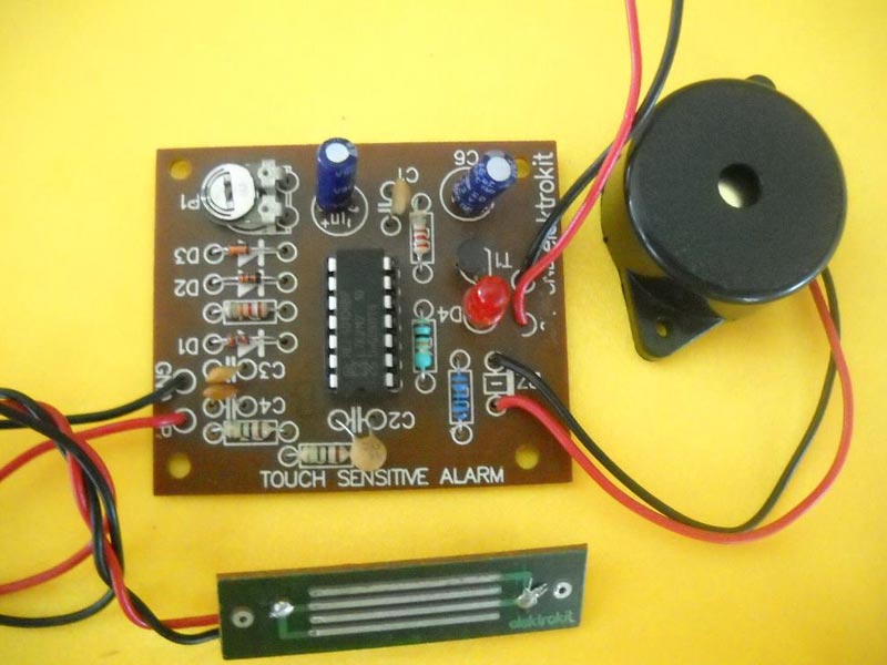
Touch Sensitive Alarm can be used in a variety of applications. But, the most practical application is for intruder detector. The circuit uses Schmitt Trigger Inverter IC1, together with a self -oscillating piezo-electric buzzer and handful of other components. Our esteemed customers can avail Touch Sensitive Alarm at economical price.
About the Circuit :IC1 consists of six inverters, out of which five are used here. One of the inverter forms an oscillator with frequency around 1MHz. The frequency is determined by R1/C2. The oscillator output is given to second inverter, which in turn is AC coupled to a full wave rectifier circuit. As long as the door handle (or a metal plate) is left untouched, the oscillator output will alternately switch the input above and below its two trigger voltages. Output will thus switch alternately low and high at clock rate to drive the rectifier circuit.
When metal plate is touched, most of the signal from the oscillator will be capacitively shunted to the shield ground, which forms a pseudo earth. As a result, output of at pin6 becomes high, transistor T1 becomes on and buzzer sounds an alarm. It remains on as long as contact is made with the door handle. Also, LED D4 lights, which gives visual indication. Simple delay network consisting of P1, C1, and D3 provides minimum delay when momentary contact is made with the touch plate. The delay is varied from 2 to 20 seconds with the aid of P1.
Note : External shield ground must be provided to a small aluminium foil for effective sensitivity only in case of a battery supply.

Earthquake/Vibration Alarm converts mechanical vibration into electrical vibration and gives alarm. The Piezo electric sensor is used to sense any kind of vibration /jerk. It produces small ac signal when activated by a jerk or vibration. Since it is very sensitive to any kind of vibration it can serve as earthquake alarm also. A piezo electrical sensor is available in market in the form of a round disc. It has two terminals for output. When we want to use it, it can be placed on the surface or can be adhered to the surface with the help of cello tape or a general purpose chemical adhesive. When the surface encounters any vibrations, these are transferred to this piezo sensor and it produces a signal.
About The Circuit : A simple circuit is built around a 555 timer IC. The output from sensor is fed to a transistor T1. Capacitor C1 and Resistor R1 act as fixed bias to the transistor T1. T1 amplifies the signal and delivers amplified output at the collector. This output is again fed to another transistor through ac coupling in order to further amplify the signal. Since T1 is weekly biased, it automatically rectifies the ac signal and only pulsating dc waveform is amplified and delivered by T2. Output of this T2 is fed to trigger input of IC555 through capacitor C3. Capacitor C3 differentiates the rising and falling edge of the signal produced at the collector of T2. The positive going pulse will not have any effect on trigger input. However negative going pulse will trigger the timer and produce HI state at its output. This HI state will glow LED D1. Also buzzer starts sounding when the sensor signal is detected. The 555 configuration is a monostable flipflop and the signal goes on retriggering this monostable. Therefore output is continuously available as long as signal is present. VR1 sets the sensitivity of the circuit and VR2 sets the timing of the monostable. If the trigger pulses which triggers the mono are generated at delayed intervals, the output may not be continuous. TO make it continuous at even the lowest frequency of signal, VR2 should be set. The circuit can be powered either from 9 v battery or from mains through eliminator.

Shadow Alarm detects moving shadow on LDR and starts a melodious sound alarm. This shadow alarm can be used as a simple burglar alarm that produces a loud beep when somebody crosses a protected area or door. The circuit is highly sensitive and can detect the shadow of the moving person from a distance of 1 meter. It does not require an aligned light beam to make the circuit standby. The beep generated from the circuit will be loud enough to detect the entry of a person in the room or the protected area being guarded. It is portable and can be places anywhere for monitoring.
About The Circuit :The circuit uses a voltage comparator and a monostable timer to give the warning alarm on detecting a moving person. IC LM741 (IC1) is used as a voltage comparator with two potential dividers in its inverting and non-inverting inputs. Resistors R2 and R3 provide half-supply voltage of near about 4.5 volts to its inverting input (pin 2). LDR1 and preset VR1, R1 form another potential divider to provide a variable voltage input to the non-inverting input (pin 3). If VR1 is properly adjusted for the required light level, the output of IC1 will be high, which drives pnp transistor T1 out of conduction. This is due to the high potential at the base of T1. The emitter voltage of T1 will be high in this condition, which inhibits IC2 from oscillation and LED1 from lighting. IC2 is wired as a monostable timer. VR2 and C1 provide a preset time delay. As a person crosses the protected area, his shadow will be sensed by LDR1 due to change in the light intensity level and the voltage at the non-inverting input of IC1 will drop momentarily. The output of IC1 suddenly becomes low, allowing T1 to conduct. This triggers the monostable (IC2) and the alarm sounds. Adjust preset VR1 until LED1 turns off at the particular light level. Keep LDR1 facing the entrance of the room or the area to be protected. Sensitivity of the circuit depends on the proper adjustment of VR1. If VR1 is correctly adjusted, the circuit can detect a moving person from a distance of about 1-3 meters.

Microcontroller Based LED Multieffect Cheaser operates on Blink of eight LEDs with the software of PIC 16F84A. Five pins from RA0 to RA4 are used as the input pin. (i.e. R11 To R15).
These pins are pull-uped with 10K ohm resisters. So, when a switch isn't pushed, the input becomes H level (+5V) and when a switch is pushed, it will become L level ( 0V ). When the switch closes, the chattering occurs. The chattering is the phenomenon which occurs with the bound of the point of contact. The opening and shutting of a point of contact is repeated in short time.
We don't put the prevention circuit of the chattering at the circuit this time. When the software detects that the switch is closed once, the blink processing of LEDs are executed in the time which is longer than the chattering. Eight pins from RB0 to RB7 are used for the output pin.
The anode side of the LED is connected with +5 V and the cathode side is controlled by PIC via the resistor. So, when the output of PIC is H level (+5V), the LED goes out and when the output of PIC is L level (0V), the LED lights up we using high brightness type LED to make an current flow little.
Note :

We bring forth efficient Smoke Detector, which alerts people as soon as it detects smoke anywhere in the building. The sensor assembly consists of white LED D1 and Photodiode D2, which are mounted face to face in an enclosure such that when smoke passes through this enclosure, a noticeable alarm is raised. We offer Smoke Detector in different specifications in order to meet divergent demands of the clients.
About the Circuit :

Sensing darkness and LED light in the room with battery backup and available for Rs 390/-, the Automatic Night Lamp Cum Emergency Light uses a light-dependent resistor (LDR) as the sunlight sensor and a total of 9 high-brightness white LEDs. Separate resistors are connected in series with each row of the LEDs.
The working of the circuit is very simple. During daytime, light falls on the LDR1 and it offers a low resistance. As a result, both the transistors (T1 and T2) do not conduct and the LEDs (D1 through D9) do not glow. On the other hand, during nighttime, the light does not fall on LDR1 and it offers a high resistance. As a result, transistors T1 and T2 conduct and the LEDs (D1 through D9) glow.
Assemble the circuit on a PCB and enclose in a cabinet. Connect the LEDs (D1 through LEDD9) and LDR1 on top of the box and place the unit such that during daytime the sunlight falls directly on LDR1. For powering the circuit, use a 9V battery & 9-0-9V/500mA transformer. The power supply rectifier diode D11 & D12 & filter capacitor C2 is already in the circuit.VR1 for adjusting the light intensity for LDR.

The 16 Tune Musical Door Bell gives 16 different tunes by pressing switch sixteen times. This simple 16 Tune Musical Door Bell finds application as a doorbell as well as telephone intruder music player, toy or attention call bell. The heart of the circuit is an APM993D named as IC1. IC APM993D is a programmed 1024 note ROM memory, which generates 16 musical tunes when it is triggered. The main feature of this IC is that it has inbuilt tone generator, rhythm generator, modulator, oscillator, frequency divider and preamplifier. So a very few number of components have to be connected externally to set up timing and to build an external AF amplifier/driver circuit.
About the circuit :When switch is pushed on, voltage at pin 10 triggers IC APM993D. After triggering, IC plays a musical tone. 16 musical tones can be heard simultaneously on pressing sixteen times. Transistor T1 is used as an amplifier connected to chip preamplifier output at pin 14 to drive 8W loudspeaker. Resistor R1 controls the tempo i.e. the speed at which tune is played. Tempo can be varied as per choice by changing the value of R1.

Infrared Burglar Alarm gives alarm on interruption of IR beam. The entry of undesirable person from the gate produces an alarm which is much more pronounced and the alarm can be either fitted inside the house or outside as desired. By using this circuit, residents need not spend on watchdog or watchman to restrict the entry of unwanted elements. This IR circuit i.e. transmitter and receiver is mounted on two side of gate. The intruder while passing through the gate obstructs the IR (non visible) beam and produce a remote alarm to be fitted as desired by the house owner.
About the circuit :

We are a noted Manufacturer and Supplier of Four Channel On/Off Control Circuit in India. This four-channel control uses only one D type latch IC1, and some associated circuitry to control four different gadgets. To control more devices, identical circuits, in multiples, can be used. IC1 consists of eight latches, out of which four are used here. The circuit incorporates the following features :
About the Circuit :
Details
The following table will help you to select the channel and corresponding on/off switch.
| Channel | On Switch | Off Switch |
|---|---|---|
| Channel-1 | S1 | S5 |
| Channel-2 | S2 | S6 |
| Channel-3 | S3 | S7 |
| Channel-4 | S4 | S8 |
| All Channels | S9 | S10 |
Power Supply : It requires +5V DC supply for circuit operation and +12V for activating the relay as shown in the circuit diagram.

We are a noted Manufacturer and Supplier of Infrared Remote Switch Circuit in India. The circuit described here can be used for any simple on/off function such as controlling a lamp or fan. The major advantage is that this circuit is absolutely free from ambient light interference and provides controlled range of about 10 mt without the use of any focusing lens. Transmitter and receiver circuits are described below:
Transmitter Circuit :Transmitter section consists of a power supply, an oscillator and an output stage. The circuit diagram for transmitter is shown in fig. IC1 is wired as an astable multivibrator with a center frequency of about 26 KHz. When switch S1 is pressed, the circuit gets energized, output of IC1 is a square wave. The infrared LED connected at its output transmits IR beams modulated at the same frequency. The oscillator frequency can be shifted slightly by adjusting preset VR1.
Receiver Circuit :
Protect the circuit :High frequency produces a lot of harmonics act as a source sustained noise. To minimize this effect, the sensor should be covered with a dark red glass plate light from other sources like fluorescent lamps. IR candescent lamps and sunlight do not have any effect on the circuit.
Calibration :
Amongst the prominent Mini Project Kit Manufacturers and Suppliers in Maharashtra, India, our name stands distinguished owing to the quality we offer. We have a newfangled infrastructure for developing the Mini Project Kits of the premium quality. Each component in this kit is made to precision to add to its usability for the longer run. Inside the kit, you will also find an instruction manual. We are committed to providing quality at every front, be it for the products or the services. Thus, we make sure that the Mini Project Kits are safely delivered at your doorway within the pre-decided time frames.

Musical Entrance Alarm has a musical light operated burglar alarm. The circuit generates musical tone when light falls on LDR gets interrupted. This can be used to detect an unknown person when he tries to open the door. Working of the circuit is based on LDR and musical tone generator IC APM993D (IC1). LDR triggers IC 993D when light falls on it gets interrupted by a person. IC 993D is a programmed 1024 note ROM memory, which generates 16 musical tunes. It has inbuilt oscillator as well as preamplifier circuit.
About the circuit :

Two Digit Counter Circuit is used as model racetracks. As compared to mechanical lap counters, which suffers from poor contacts or the mechanism easily jam, this electronic lap counter is based on the principle characteristics of phototransistor. Hence, it has very high reliability and efficiency. The counter can count maximum 99 laps, which can be preset to individual requirements. The display is shown on two 7-segment displays.
About the Circuit :The circuit uses six ICs and two 7-segment displays. The triggering circuit is built around IC1, which consists of four NAND gates and phototransistor T1. IC2 and IC3 are used as a counter ICs, IC4, and IC5 are used to drive two 7-segment displays.
When any object passes the “checkpoint”, it interrupts the light falling T1. T1 has a feature that in presence of light it has very low resistance but when light falls on it interrupted its resistance increases to a very high value. Hence the flip-flop designed around IC1 gets set, which provides clock input to IC2. Now IC2 starts counting. After counting from 0 to 9 it gives clock input to IC3 and now IC3 starts counting. Thus, we can count maximum 99 laps. The output of IC2 and IC3 are in BCD form. To convert this BCD logic into 7-segment display, IC4 and IC5 are used, which are BCD to 7-segment display driver. The display is reset by pressing switch S1.
Power can be restored and the counter reset by pressing the Reset switch RS. The phototransistor T1 should be mounted in a cylindrical tube to screen it from ambient light, which might otherwise keep the phototransistor resistance low and block the circuit. The sensitivity may be adjusted by P1.
Power Supply :The circuit requires a DC power supply of 5V, which is designed using regulator IC6. Diodes D1 and D2 are used as a rectifier diode and capacitor C1 are used as a filter capacitor.

Speed Control Of Dc Motor is developed to control any speed of DC motor using 555 & Mosfet. A PWM circuit based on timer NE555 is the heart of this Speed Control Of Dc Motor. NE555 is wired as an astable multivibrator whose duty cycle can be adjusted by varying the POT VR1. The output of IC1 is coupled to the base of transistor Q1 which drives the motor according to the PWM signal available at its base. Higher the duty cycle the average voltage across motor will be high which results in higher motor speed and vice versa. The following project is a PWM motor control. It is very easy to be built and it can efficiently control all DCmotor to rpm as low as 450 rpm . It uses ONLY one 555 timer and a few other components, and it can be powered also directly from the PC power supply, from the 12 Volts line. DC Motor Speed Controller Circuit Using NE555 PWM switching will create a series of PWM pulses and will be driven directly to the gate of the MOSFET. The MOSFET is chosen to be big enough to carry enough loads, up to 9.2 amperes. You can choose a MOSFET according to your needs. The MOSFET will generate enough power so that the motor will start revolving. The capacitor across the MOSFET is the solution to the 'kicking sound'. The MOSFET will send to the motor pulses according to the pulses generated from the 555. If you remove the capacitor, you will definitely hear this annoying sound. The capacitor will smooth the voltage across the motor and therefore the power driven to it will be smooth, avoiding the torque kick.

Microcontroller (89C51) Based Seven Segment Number Selector displays 0 to 9 numbers by pressing push on switches. This circuit is a simple application built around the seven segment display. The circuit has ten inputs corresponding to digits zero to nine. Whenever an input is pressed the corresponding digit is displayed on the seven segments. The microcontroller used is AT89C51 which belongs to the 8051 series of microcontroller. The circuit can be divided into two units: the controller unit and the display unit. The controller unit consists of a microcontroller circuit. The microcontroller used here is AT89C51. The display unit consists of a seven segment circuit which is interfaced to the microcontroller. The circuit is similar to the seven segment circuit with the only difference that here we have ten input pins. Each input pin corresponds to one of the digits to be displayed on the seven segments. Here the pin 0 to pin 7 of port P3, pin 6 and pin 7 of port P 1 are made the input pins. The output is sent to the seven segments through Port 2 of the microcontroller.

We are offering Sound Operated Timer Circuit. The circuit described here is that of an electronic switch which can be operated by sound of a clap. The circuit can be used in sound operated motor-driven toy car or any other gadget as per requirement. About the circuit : the circuit uses the timer ic, a condenser mic. The mic is used to convert the sound signal into electrical signal. These signals are amplified by transistor t1 and given to the ic the output of ic1 is from pin number3 which is used as reference input of transistor t2 which is used to drive the relay.with a clap a relay will be energized and will remain on as per setting of vr1.the minimum time for which it would remain on is two minutes and maximum is five minutes, which is sufficient for a toy car. If the on time of relay is to be increased then the value of c3 will be increased and delay wants to decrease then the value of c3 should be less.it can be operated on 6v to 12v dc after changing the relay according to required voltage.

Our valued clients can avail Touch Switch from us. Touch Switch makes possible to turn on/off a device by touching a metal plate successively. The circuit uses timer IC555 (IC1), which is followed by master slave JK flip- flop IC4027 (IC2). On touching the plate, IC1 gets triggered and IC2 makes output at pin1 high and low on first and second touch respectively. Accordingly relay becomes on and off successively.
About the Circuit :When the metal plate is touched, IC1 performs one monostable operation. Output at pin3 of IC1 goes high. This pulse acts as a clock input at pin3 of IC2. When clock is high, master flip-flop of IC2 is enabled and data inputs (J and K inputs at pin5 and pin6 respectively) are not effective at this transition. When clock goes low, slave is enabled and data is transferred from master to slave.
During the first touch, output Q at pin1 of IC2 goes high. Transistor T2 conducts and relay becomes on. Now during the second touch, output Q becomes low. Because in master slave JK flip flop output changes to the complement of last state its state at successive clock pulses. Thus T2 gets cut off and relay becomes off.
The circuit also gives visual indication of touch switch using two LEDs. When Q becomes high, T1 turns ON which makes the red LED D4 turns OFF and green LED D5 glows indicates that the device is on. Similarly, when Q becomes low, T1 cuts off which makes red LED D4 to glow and green LED D5 to goes OFF. This indicates that the device becomes off.

Microcontroller Based Programmable 4-Digit Code Lock System can change the password with alarm useful for Door Lock, Device Lock, Car Lock, and Locker System (Using 89C2051). Today is the world of automation. When we are talking about automation, we must think about microcontroller. Microcontroller finds its application in each and every automation control like Remote controllers, Hand-held communication devices, automatic and semi-automatic washing machines, security system, telephone printing machines, automobiles, indicating and measuring instruments. The project described here being also a microcontroller based project, used for security purpose. The use of microcontroller in this project is to store the data, process data and change data according to the user requirement. This is possible because microcontroller has CPU, memory, I/O ports, timers/counters, ADC/DAC, serial ports, interrupt logic, oscillator circuitry, and many more functional blocks on single chip. Hence it reduces the cost of hardware. Also there is no need to connect external RAM for memory storage. This is the most important feature of microcontroller. There are various types of microcontrollers available in market. The examples are Intel MCS-51, PIC family by microchip, ATMEL 89CXX, 89CXX51. The microcontroller used for this project is ATMEL-89C2051. The important features and pin description are given later. The code lock system described here uses a very simple hardware as shown in the circuit diagram. IC1 and IC2 are bus driver and latch IC’s, which are used for transmitting and receiving data from microcontroller i.e. it is the interface between microcontroller and keypad logic. At pin2 and 3 of microcontroller, relay drivers using transistors are connected. IC5 is a regulator IC, which gives 5V regulated power supply. Software is used to store code, process code according to user requirement and gives output at corresponding port. The device activates an output when correct access code has been entered on a keypad. This code consists of four digits in the range 0 to 9. The code can be changed by the user and is also remembered when the power is off. The circuit is eminently suitable as an electronic door-lock, the switching section of a burglar alarm or as an ignition-blocking device. The output is inactive when the circuit is powered up or has been reset. When the ‘*’ key is pressed, followed by the 4-digit code, the output will go to the 5V level and the relay connected to pin3 of microcontroller will be energized. If the code is incorrect, the wrong alarm LED connected to pin2 of microcontroller will glow. Also relay will be energized which is connected to any noise-generated device. When the code lock is used for the first time, the access code is 1234. This can be changed to, for example 4567 by first pressing ‘0’ followed by ‘#’, then the original code, then the new code. If something has gone wrong, the original code remains valid and error signal will sound. The procedure for operation of the code lock is given below. How to operate Code-Lock: Open the Lock: 1. Put on Power. 2. Press ‘*’ key ‘LOG-IN’ LED D3 will glow. 3. Now enter the old password. 4. If Code is correct ‘SYS-ON’ LED D2 will glow and lock is open. 5. If code is incorrect wrong alarm LED D1 will glow for 1 second. 6. Repeat above steps to try again.
Change the Password :
About 89C2051 Microcontroller :ATMEL 89C2051 is CMOS 8-bit Microcontroller. It has flash programmable and erasable read only memory. It is a 20-pin device. The pin details are given below. It has 15 digital I/O lines. The pin descriptions are given below. 89C2051 provide cost effective, compact and flexible solutions to many industrial applications. It uses only port-1 and port-3. Details of pin-out: X2 (pin-4):- Output of inverting amplifier that forms the part of the oscillator and input to the internal clock generator. In case of external clock, it must be connected to X2. X1 (pin-50):- X1 is the input to the inverting amplifier that forms part of the oscillator circuit. In case of external clock, this pin must be connected to ground. Vcc (pin-20):-This pin is connected to +5V power supply. Vss (pin-10):-Vss is the circuit ground. RXD (pin-2):-serial input. TXD (pin-3):-serial output. INT0 (pin-6):-external interrupt. INT1 (pin-7):-external interrupt. T0 (pin-8):-Timer/Counter0 external input. T1 (pin-9):-Timer/Counter1 external input. Software: Software for this code lock system is already programmed in 89C2051. You have to only insert IC in IC socket and run it.

Auto Reset Over/ Under Mains Voltage Cut- Out is an over/under voltage cut-out that will save your costly electrical and electronic appliances from the adverse effects of very high and very low mains voltages. This circuit able to switch and cut off the mains power from reaching the connected appliances once the input voltage crossed over or below the dangerous thresholds. However due to the over simplicity of the design, involving just a couple of transistors, the circuit has its own limitations, the major limitation being less accuracy and considerable hysteresis, resulting high threshold gap of more than 60 volts between the high and the low limits.
The present design of a high voltage and low voltage cut off circuit is not only highly accurate but also provides visual indications regarding the relevant voltages insteps. The accuracy is so high that virtually the thresholds can be separated and sensed within 30 volts range. The incorporation of op amps in the circuit equips it with the above feature and therefore the whole idea become very much reliable.
About the circuit :The op amps, A1, A2, A3, and A4 are obtained from a single IC 324, which is a quad op amp IC, means consists of four op amp blocks in one package. The IC is outstandingly reliable and easy to configure and hardly poses a problem with its functioning, in short it has robust specs and is too flexible with most of the configurations. The two op amps are rigged as voltage comparators. The inverting inputs of the op amps are clamped to a fixed reference value of 12 volts which is done through a resistance/zener network for each of the op amps discretely. The non-inverting input of A1 are connected to the power supply of the circuit through a voltage divider network formed by the presets VR2 .The presets can be adjusted as desired to flip the outputs of the respective op amps when the relevant input level crosses the reference level set over the inverting inputs of the respective op amps. This special arrangement ensures that only one relevant LED is switched ON in response to the rising or falling voltage levels from the op amps. Two Transistor are connect to the output of op-amp and the LEDs in series so that the transistor conduct with the relevant LEDs during high and low voltage levels, specified as dangerous thresholds. The conduction of the transistor instantly switches the respective relay. The poles of the two relays and the poles of the relays are connected in series before supplying the output through them to the load. The series connection of the contacts ensures that if any one of the relay conducts, cuts of the mains supply to the load or the connected appliance. Suppose at certain normal levels A1, A2 are all conducting (outputs high), at this point only the LED connected to Resistor would illuminate, because its cathode receives the required negative from the output transistor, whereas the cathodes of the lower LEDs are all high because of the high potentials from the above op amps. The LED connected to Resistor also remains shut off because op-amp output is low. The above results appropriately influence the respective opt couplers and the relays such that the relays conduct only during dangerous low or dangerous high voltage levels detected by only A1 and A2 respectively.

Light Operated Switch is a very commonly used circuit to control outside lighting or used for driveways and garage entrances. Light Operated Switch is very simple and inexpensive design, which uses timer IC555 (IC1) and Light Dependent Resistor or LDR as a sensor. LDR has unique feature that in presence of light it has very low resistance. However, when light falls on it is interrupted, its resistance increases to a very large value. This feature is used to trigger IC1, which operates in monostable mode.
About the Circuit :In presence of light, LDR or R3 as shown in the circuit diagram has very low resistance. Hence, voltage at trigger pin2 of IC1 is above 1/3Vcc. In this case, the output of IC1 at pin3 remains low and relay is not energized.
As soon as light falls on LDR gets obstructed due to the movement of some objects, the voltage at pin2 goes below 1/3Vcc. At this moment, IC1 is triggered and the circuit is switched on. The output at pin3 becomes high and relay is energized. The output remains high as long as light is obstructed.
Here diodes D3 and D4 are used as a rectifier diode and capacitor C3 as a filter.
Calibration :The preset VR1 is used to adjust the sensitivity of the circuit. Initially make lights off on LDR and slightly go on adjusting VR1, till the circuit is switched on.

Griposcope Circuit makes it possible to know the muscle power. Griposcope can also be used as a lie detector and moisture level monitoring or simply for conjuring tricks.
Two probes are left to calibrate you. Hold them tight. As you, increase your grips on these wires, the LED dot jumps into lower order. The stronger the grip, lower the position of the dot. If you cannot keep a steady hand, the LED dot oscillates up and down.
About the Circuit :Griposcope is designed using linear voltage display IC3914 (IC1). Griposcope consists of 11 comparators and associated network in a single chip packed.
The resistance of the body RB, applied to the input pin 5 of IC1 changes according to the grip of the leads. The proportional voltage is applied to the inverting input of each 11 comparators, which compares this voltage with non-inverting voltage set by battery, pot VR1 and chain of 1K resistors internally designed. Depending on the output of comparators, corresponding LED will flash. The position of glowing LED changes with the change in resistance across points X and Y. As the position of glowing LED increases, strength decreases. Glowing of Green LED D1 indicates minimum strength.
Calibration :Preset VR1, VR2, and resistor R1 can set the sensitivity and the range of deviation. In the absence of body resistance RB, VR1 is adjusted so that LED D10 glows.
Note on Probe Wires :Two highly insulated wires such as multimeter probes, can act as a sensor. The area of contact between the probes and skin plays an important role in varying the resistance between them.
Power Supply :A mains derived power supply is not used for the circuit. Operational voltage is derived from two 1.5V batteries. The operation of the device becomes critical if the supply voltage falls below 2.25V approximately.
Resistor R2 sets the current to around 1mA through the LED. The power set by the device is well below 40mW in all the positions.

The Dual Power Supply Circuit gives regulated Dual output of ±5V to ±15V and is available at a reasonable price of Rs 380/-. One often realizes the need for power supplies, which provide dual positive and negative output rails. This is particularly true with circuits, which contain operational amplifiers. Such devices require closely regulated supply rails of typically ±5V, ±9V, ±12V or ±15V. Integrated circuit voltage regulators are available in a range of output voltages and usually feature internal fold-back current limiting as well as thermal shut-down. A simple method of meeting such a requirement is shown in figure. Here two fixed voltage regulators of opposite polarity, are used in conjunction with a dual secondary transformer and single bridge rectifier. The current rating of the regulators should be greater than, or equal to, the maximum load current. Circuits which are solely based on operational amplifiers rarely require supply currents in excess of 100mA and thus 78XX/79XX series regulators will usually be adequate. The IC number and transformer rating for different output voltages are given in table.
About the Circuit :As shown in the circuit diagram, AC input is given through transformer. The transformer rating depends on the output DC voltage as shown in the table. The AC output voltage obtained from the transformer, is rectified through bridge rectifier designed using four diodes D1 to D4. Capacitors C1 and C2 are used to filter the AC signal. The rectified filtered output is given to regulator IC1 and IC2. The output of IC1 and IC2 gives the fixed DC voltage depending on the voltage capability. This output is again filtered through capacitor C5 and C6. LED D5 and D6 glows, which indicates positive and negative output.

In many places such as hostels, apartments, school/colleges, hospitals, etc, overhead tanks are used for storing the water. As the requirement of water is large, controlling of tank is very important. Overhead Tank Controller is a specially designed circuit to overcome this problem. Overhead Tank Controller has two sensors named as HIGH and LOW immersed into the tank with reference, which is at positive potential. The motor is on until the tank is full. When it reaches to HIGH level, the motor automatically turns OFF and it remains OFF until water level goes below LOW sensor and then it becomes on again. Thus, Overhead Tank Controller prevents the overflow of water.
About the Circuit :

Twilight Switch is a light dependent switch, which automatically turns ON when it gets dark. This is one of the simplest light dependant switch, which automatically turns on when it gets dark. It is based on the characteristics of light sensitive resistor R1. During the day time, the value of R1 is very low. But in dark, it has very high value. This feature makes this simple circuit to operate as an automatic twilight switch.
About the Circuit :
Calibration :

The traffic lights, we see can be designed around an inexpensive ICs and enables us to understand the function of traffic lights in simple way. Simple Traffic Light kit is very much helpful for children to understand and follow the traffic rules.
About the Circuit :

Many people forget to switch off lights, especially the toilet light at night. This results in wastage of electric power. Toilet Lamp Controller is specially designed to overcome this problem. After switching on the toilet lights, Toilet Lamp Controller automatically turns off the lights after a few minutes, which can be preset to individual requirements. You can set timing from 20 sec to 5 min.
About the Circuit :Toilet Lamp Controller is built around the popular timer IC, used in monostable mode. For triggering in this mode, the IC requires a negative pulse, which brings the trigger input below 1/3Vcc. The normally low output then goes high for a period determined by the RC network comprising VR1, R1, and R2. The output pulse length is 1.1RC seconds approximately.
The tolerance of timing components makes it impossible to get highly accurate timing. This is overcome by the inclusion of potentiometer P1. The threshold voltage, which is 2/3Vcc can be raised or lowered to get accurate timing by P1.

Fire Detection System raises an alarm when temperature increases due to fire. Fire alarm circuit is used to sense the fire as well as temperature. Here reverse bias Germanium (GE) diode is used as a heat sensor. At temperature about 60oC and above, reverse resistance of GE diode drops and makes pin4 (reset) of IC 555 at logic high level. Hence IC generates output pulse and raises the alarm. It has household as well as industrial applications.
Circuit operation :

Metal Detector detects the presence of metal by giving audible warning. This project indicates the presence of ferrous as well as non-ferrous materials depends on the absorption of magnetic energy. An inductor, which forms part of a tuned oscillator circuit, radiates a magnetic field. When a metal object is introduced into this field, enough magnetic energy is absorbed to cause the oscillator to stop working, which causes the output of IC1 high. Transistor T2 turns on and buzzer raises the alarm. IC1 is a Schmitt Trigger IC, which gives output according to the upper and lower threshold voltages set at input pin2 and pin3 respectively.
About the Circuit :In the circuit diagram, L1 and C1 form an oscillator circuit operates at a frequency of about 70KHz. L1 also serves as a sensor. Because of the high value of resistor R1, the oscillator only just operates. This is desirable; otherwise any losses in the tuned circuit would easily be replenished by the transistor T1.
When the metal object enters in the field induced by L1, the oscillator output is detuned. This output is rectified by diodes D1 and D2 and given to pin2 which is the upper threshold voltage of IC1.This voltage is below the lower threshold voltage at pin3, which is set by R7, R6 and P1. Hence the output at pin6 goes high and T2 turns on. Piezobuzzer connected at the collector of T2 sounds an alarm.
Note : Inductor L1 is not intended to be fitted on the circuit board.
Calibration :

We bring forth the best Temperature Switch for our valued clients. We are a reliable Manufacturer and Supplier of Temperature Switch, operating from India. Temperature Switch automatically switches ON, when the temperature rises to about 60oC. Temperature Switch is a very simple circuit build around IC1, which is operated in monostable mode and temperature sensor diode D1. At temperature about 60oC, the sensor triggers IC1, which makes output of IC1 at high level and energizes the relay. In addition, Temperature Switch turn OFF as temperature goes below 60oC.
About the Circuit :

Our esteemed customers can avail Electronic Dice from us. A dice when thrown can take any position to give the players random number out of six. The effect can be very well experienced and even commercially exploited to play actual game of electronic dice with this kit.
In the conventional game, a dice is thrown and the player watches what position it takes out of six possible positions. The dice needs to be positioned randomly at every throw. This effect is practically implemented by a small inexpensive electronic circuit.
About the Circuit :

Infrared Obstacle Detector is useful in many applications. One of the most demanding applications can be a tool for blind person. Latest technologies like Automatic (driverless automobiles, train anti-collision, electronic toys like car, train, and robotic gadgets etc.).
The principle involved is infrared (IR) emitter and receiver. When IR emitter emits light and it becomes incident on an obstructing object, it gets reflected. This reflected light is picked up by a sensitive receiver and can be converted to suitable signal to alarm the user regarding the obstacle. Absence or reduction of received light decides the presence or absence of the obstacle.
Modulation is the answer to make our signal stand out above the noise. With modulation we make the IR light source blink in a particular frequency.
Another purpose this modulation solves is to make the circuit more sensitive and able to work with higher range i. e. to detect obstacles from more distance, the light emitter is modulated at about 38 KHz.
About the Circuit :

Today the ‘fresh air’ can only be imagining. Because, nowadays due to the big industrial developments, the air becomes so polluted that most of the people have to suffer from lot of diseases. But now because of the magic of this small unit, you may say bye-bye to all of these disorders. Although it has lot of advantages, it is a very simple and inexpensive circuit that the people can use it very easily for several years. Room Air Freshener Circuit works on the principle of ionization, which, helps to remove polluted air
Pure air has positive and negative ions in 1:1 ratio approximately. Air becomes polluted due to the ionic imbalance. Ionic imbalanced air has less negative ions and more positive ions. The idea mainly employs here is to apply a high negative voltage, several KV in fact, to a sharply pointed emitter. The negatively charged air is repelled from the emitter resulting in an ‘ion breeze’ you will feel if you put your hand close to the ionizing point.
About the Circuit :
Testing :
Precautions :Although the circuit as a whole has a very high output resistance, individual capacitors don’t work, so please take care when you are testing the circuit. The capacitors will retain their charge for some time after the circuit is unplugged, and a painful shock can be received from the back of the PCB if you are careless. The circuit can be discharged by touching the mains plug to the ionizing point for a few seconds, and just to be certain you can run the mains plug down the line of diode connections on the PCB.

Dual band (900MHz/1800MHz) GSM/GPRS Modem is a very advance SIM900/Sim900A GSM module SIM900/900A GSM/GPRS Modem follows plug and play operation with on board RS232 interface for communication and follows standard AT command set. SIM900/900A GSM/GPRS Modem is highly popular due to its efficient working and high quality.
DEtail :

Nowadays sound operated switches becomes very common in our modern life. Here is a simple and inexpensive design of clap operated switch, which is very easy to assemble by hobbyists at any level. With this circuit, the device switches on by first clap and it switches off by the next clap. The circuit is designed using four transistors and a very few number of components. About the Circuit: The sound signals generated by making a clap are received by condenser microphone, shown in the circuit diagram. Microphone converts these sound signals into equivalent electrical signals. These signals are amplified by transistors Q1, Q2 and Q3. The amplified signal is given to driver transistor Q4. During the first clap, Q4 turns on and relay connected to the collector of Q1 gets energised. On next clap, Q4 turns off and relay goes off. Again when the next clap comes, the procedure repeats as above.C1, C2 & C3 are coupling capacitors. D6 LED indicate the realy is on condition.

The name of the project itself suggests its application. Liquid Level Indicator With Alarm can be used for level control in hydro culture project. It is also used for kitchen purpose like detecting the level of water in washing machine. The main feature of this circuit is that it shows each level in meaningful English letters. It displays letter ‘E’ for Empty, ’L’ for Low, ’H’ for Half, ’A’ for Above Average and ‘F’ for Full Tank. The sensors for each level are immersed in tank. The other end is connected through four NOR gates N1 to N4 which uses IC 4001(IC1). The output is then given to IC 4055 (IC2) which is BCD to seven segment display driver IC. The level of fluid is indicated on 7- segment display. Also when the tank is full, the piezobuzzer raises a noticeable alarm.
About the Circuit :As shown in the circuit diagram, when tank is low, N1 of IC1 gives output high, whereas N2, N3 are at logic zero. Their logics are applied to BCD inputs of IC2. Hence IC2 drives 7- segment display according to the BCD Code present at inputs. For low level BCD logic is ‘1010’. For this logic, display will indicate ‘L’. As the level increases, BCD logic changes, and display will indicate accordingly. That is ‘H’ for half and ‘A’ for above average. You can see the code generation table or logic table.
Note that there is no display pattern like ‘E’ or ‘F’ available from IC2. Therefore to obtain these pattern transistors T1 and T2 are used. These transistors blank out the unnecessary segments from 7- segment display. It can be seen that the letter ’E’ is generated by blanking ‘b’ and ‘c’ segments while it decodes digit ‘8’. Letter ‘F’ is obtained by blanking segment ‘b’ while it decodes letter ‘P’.
In addition the piezobuzzer connected to transistor T3 raises alarm when tank is full. In this case, N4 of IC1 gives logic high and makes T3 to conduct.
Note :

Quizmaster Board is designed to be used in quiz shows. Quizmaster determines who is first to press an answer button, is a problem since more than one person may appear to have pressed the button at same instant of time. To differentiate between the minute time differences in between two persons pressing the buttons is almost impossible for human being.
Only electronic device can do it with accuracy and therefore our Quizmaster is very popular now days with growing competitions being arranged. The circuit given here helps to make students familiar with an interesting device and helps develop understanding and interest of electronics bedsides commercial utilization.
About the circuit :As shown in the diagram, the circuit is designed around ICs 4012 (NAND GATES) and 4013 (D Flip flop).
The IC 4012 which has two dual FF with SET and CLEAR inputs; is used to set/ reset FFs. When the competitor presses a button/push switch (say S1), the FF1 gets SET (Q = 1, Pin13) irrespective of D and clock inputs. However to avoid action by noise pulses, the D input and Clock input is connected to logic HI.
This action forces Q output to go HI and Q- (pin12) to go LO. Hi at Q output will force LED D1 to glow through driver transistor T1. The Q- output is connected to inputs of all NAND gates
(N2, N3, N4) in the remaining FF circuits. The NAND gate outputs are in turn connected to CLEAR input of FF ( FF2, FF3, and FF4). This will produce LO state at all other FF outputs (Q) by virtue of being cleared.
The circuit is reset after a round is finished before the next round is to be started. The reset switch S5 shown here forces one input of all.
When next time another button is pressed, the corresponding FF gets SET and all other FFs gets reset thus glowing another corresponding LED.
Thus with press of a push switch, corresponding LED glows and all others get inhibited. The circuit also has a common buzzer, which gives audio alarm when any of the LED glows so as to attract attention of viewers and judges. The common buzzer is activated by another set of transistors driven from same output of FFs. All the buzzer signals are ORed through D5 – D8. The circuit can be easily extended to more number of competitors. For each additional competitor/participant an extra FF and a NAND gates is required to be connected. These NAND gates can be Red and the same result can be obtained. To avoid possibility of interference on account of long length of wires , the low impedance of RC network connected to SET input has to be kept low .If such problem is faced , value of R1 –R8 can be reduced to 1k.

The Clap Operated Staircase Light is a useful device for staircase light, which can be turned ‘ON’ by clap & ‘Off’ as per delay setting. The Clap Operated Staircase Light is a solution for common habit of switching the light on and forgetting the same. Stairways, corridors or small indoor passages often tend to be dark throughout the day irrespective of the outdoor ambient light conditions. Therefore keeping such passages illuminated all the time becomes imperative, however this leads to unnecessary wastage of electricity.
This 9-12V battery-operated circuit triggers an Lights on when a sound is detected. It can also be used staircase light delay ON time setup as per your choice, which is as per person taking time to up or down period to complete staircase distance. The circuit has an ordinary condenser microphone MIC1 as a sound sensor. Sensitivity of this microphone can be changed to some extent by changing the value of the bias resistor R1. When the circuit is powered by a 9-12V battery supply to the circuit, transistor T1 acts as pre amplifier and T2 is again amplification the week signal of the mic and condenser C3 charge /discharge pulse fed to the IC1 of pin 2. This IC1 is in monostable mode the time starts up to the capacitor C5 will be discharge, and output pin 3 of IC 1 get firing the transistor T3 conduct, hence relay will be 'ON' and start the light / Bulb through relay in the series of the mains 220v will be 'ON'. The time period can be adjust by setting to VR2 Preset. VR1& R9 use for pull-up resistance for adjusting the avoid chattering the pin 2 of IC1.

We are offering Bcd to 7 Segment Display Circuit. Introduction : We see alphabets and numbers on many electronic machines in the market and public places. Seven segment display is now a days so popular that no electronic indicator can do without it .Ever gadget designer should learn about it. To display any number in English we require seven segment display. The drivers for driving these displays are abundantly available. As well as decoders from binary to seven segment code are also available. With the help of these decoders and drivers we can incorporate these display in any system where numbers are to be displayed. About the circuit : The IC 7447 is a decoder driver for seven-segment display, common anode CA type. It converts BCD code to seven-segment code and drives each segment of LED in seven segments LED display. Only current limiting resistances are required to be used in each segment. The seven segment displays fall in two categories of the CA (common anode) and CC (common cathode). 7- segment LEDs also have 8th segment, called decimal point. Thus it has 8 LEDs inside one body and have normally 10 pins . Two pins are allotted for common and 8 for segments (a to f and dp). CA has all anodes connected together, brought out as common pin and cathodes are available individually at terminal pins. Similarly in CC, all cathodes are connected together, brought out as common pin and anodes are available individually. When we need to glow a particular segment , we must pull it down by driving the individual pin low. Exactly same thing happens when we feed BCD code at input of 7447. It converts BCD code to seven segments as shown here in the table. The circuit here outputs the desired outputs i.e. Hi at those terminals which are required to glow as per the BCD input given to it. Besides these functions, the decoderdriver IC has additional function pins like LT, RBI and BIBRO LT (pin 3) when pulled Low shall lit all segments. This is provided to check all display segments for their functionality. RBI (pin 5) when low blanks the display only when input is BCD zero. BIBRO (pin 4) when pulled low shall put off all segments irrespective of input logic levels. This is useful when leading zero blanking is to be used to save power or control intensity. Since it is not totem pole output and has only a resistive pull up, it acts as input and output both. When used as input it can be forced low because of resistive pull up provided internally. To achieve leading zero blanking of displays in a multi digit display, RBI pin of a most significant decoder is connected to ground, and its BIRBO pin (which becomes low)is connected to next lower order decoder and thus cascading all will achieve leading zero blanking. For better understanding and grasp of the decoder and display function, the PCB is provided with facility to connect miniature toggle switches for applying individual logic signal (H & L) to all BCD inputs. This facility can be useful to practice for beginners. IC2 ( 7805) is a 5- v regulator provided to supply power to the IC 7447 and to display. Rectified DC filtered Input to this circuit can be between 8.5 to 12 volts. The decimal to BCD table and truth table for decoder are provided with literature.

Double Direction Automation Of Manless Railway Gate is related to automation in railways. Automation Of Man-Less Railway Gate (Double Direction) is designed to avoid railway accidents by notifying the arriving of trains to the station masters. Automation Of Man-Less Railway Gate (Double Direction) automatically detects the arrival of train and GATE opens. Also, as the train passes, it automatically closes the GATE. The circuit is very simple. Automation Of Man-Less Railway Gate (Double Direction) is constructed using Infrared transmitter and receiver. The use of an infrared light source is an oblivious choice for this type of application. For this application, the light beam must be invisible, which limits the choice to infrared or ultraviolet light. Ultraviolet light can cause visible fluorescence of certain materials, which makes it less suitable than infrared. In the second place, relatively powerful solid-state infrared sources and infrared sensors are available at modest cost, whereas there are no solid-state UV sources commercially available. The circuit uses here infrared LED and photodiode.
Although these devices are not exorbitantly priced, neither are they inexpensive, so in order to minimize the number of IR emitters necessary to achieve a given range the transmission system should be as efficient as possible. Since the light level received at several meters distance from the transmitter will be very low, the receiver must have a high gain. This immediately excludes the simpler types of photoelectric switch that use a continuous light beam and a DC coupled receiver. Since a high gain DC coupled receiver amplifier would be prone to offsets, temperature drift and other effects that could lead to poor sensitivity. The choice therefore falls on AC modulated light beam and AC coupled receiver.
The infrared sensors that is infrared LED and photodiode are aligned such that light beam from infrared LED directly falls on photodiode. The distance of separation should be in the range of 2 to 3 mtrs or less. When the train arrives, the IR radiations emitted by infrared transmitter and falling on photodiode are interrupted. As a result, receiver circuit detects this. The important feature of this circuit is that it can detect the train in both directions. The direction sensitive circuit is used to detect the arrival and passing of train in both directions. Alarm and Motor driver circuit is used to drive the motor and raises the alarm by connecting an electric bell to relay switch. The motor used here is a DC motor, which rotates clockwise and anticlockwise and in turn drives the railway gate.
About the Circuit :As stated earlier the circuit is built around Infrared transmitter and receiver circuit. It requires two pair of the transmitter and receiver. The first pair is kept at some distance from the station at one end. And the other pair is arranged at some distance at opposite end. For perfect execution of the circuit the distance between block A & block B should be greater than the length of the train . For driving motor, driver stage is designed using four transistors as shown in figure. When T1 and T2 gets triggered, motor rotates in one direction. And when T3 and T4 gets triggered, it rotates in other direction. The details of transmitter and receiver circuit are given below.
Transmitter Circuit :The simple transmitter circuit is shown in figure. It consists of 555 timer connected as an astable multi vibrator, driving an output transistor which switches the IR emitter on and off. The duration of the transmitted light pulses is about 10ms and repetition rate is just less than 1 KHz. The average current drawn by the circuit is about 12mA and the peak current through the IR diode is about 700mA.
The power supply for the transmitter is not critical provided the output voltage is no greater than 9V, as this could result in the maximum current rating of IR diode being exceeded. The specifications and other details are same for other transmitter module.
Receiver Circuit : The receiver circuit is shown in figure. An infrared photodiode is operated in the reverse bias mode. The leakage current of this diode varies with the light received from the transmitter, which causes a varying voltage to appear across resistor R2, the base resistor of T1. The signal appearing at the source of T1 is fed to IC1, which is used as an amplifier and limiter, P1 varies the sensitivity by altering the reverse bias voltage of the diode.
When light pulses are being received from the transmitter, a negative-going pulse train with amplitude in excess of 1V peak-to-peak appears at the output of IC1 (pin8). This turns T2 on and off continuously, charging up C11, T3 is thus always turned ON, transistor T4 is turned OFF and the logic circuit is not energized motor remains OFF.
When the train arrives from block A to block B, The light beam between the transmitter and receiver is interrupted at point A, the amplitude of the pulse train from the output of IC1 will fall, transistor T2 will be cut off, C11 will discharge. Transistor T3 will turn off and T4 will turn on. A shortly logic low pulse is applied to gate IC1. The other input of Gate receives from another IR receiver circuit. The output of gate goes high and a logic high pulse is given to clock input of IC2. As clock input transits from low to high the Q1 output of IC2 goes high. Thus, the low output is given to trigger input pin2 of IC4, which acts as a one shot multi vibrator. The output of IC4 pin3 goes high for a period determined by timing components using R6/P1/C5, which can be adjusted by preset P1 of logic card. Driver transistor T1 and T2 conducts which drives motor and the motor is on as long as pin3 of IC4 is high. At the same time transistor T5 turns on, relay gets energized which switches on bell. Also LED D9 glows which gives visual indication. When the train passes, other IR beam gets interrupted at point B, and the receiver circuit is on which gives another clock pulse to counter IC2. The next output of decade counter goes high, IC5, which is a one shot multivibrator IC gets triggered and its output goes high for a period determined by timing components designed around R7/P2/C6. The period is adjusted by preset P2 of logic card. Driver transistor T3/T4 conducts and motor rotates in another direction. Thus if gate is closed in first interruption, the gate opens in another interruption. It must be noted that the period of rotation should be same in both interruptions. Now the counter IC gets reset.
When the train goes from block B to block A, point B is interrupted first. IC2 receives first clock pulse and motor rotates in clockwise direction. When point A is interrupted, IC2 receives another clock pulse and motor rotates in anticlockwise direction. Thus the gate is controlled in both directions.
Construction : When constructing the receiver, great care must be taken with the layout due to the high sensitivity and large bandwidth. The leads to photodiode must be as short as possible, as otherwise, they may peak interference. Since the photodiode is sensitive to visible as well as infrared light, it must be fitted with an infrared filter. Direct sunlight should not be allowed to fall on photodiode, since its large infrared content could affect the diode biasing and hence the receiver sensitivity.
Calibration :The transmitter diode and receiver diode should be aligned with one another, although the radiation pattern of the one and the acceptance angle of the other are so wide that the slight misalignment will have little effect. The circuit is then checked for reliable operation at close range by breaking the infrared light beam, after which the transmitter and receiver are moved progressively further and further apart, whilst P1 is adjusted to obtain the maximum range. If the photodiode is well screened from ambient light, this adjustment will have little effect and the wiper of P1 can simply be turned clockwise.
As it stands, the circuit will function at distance of up to 3 mtrs between the transmitter and receiver. If lenses are used to concentrate the transmitted light into a much narrower beam and to focus the received light on the photodiode then much greater ranges can be achieved. However the physical alignment of the transmitter and receiver will then be much more critical.

During summer seasons, we all us knows the need of coolers. If cooler is on for long time, then the requirement of water is also very large. To minimize this problem to a large extent cooler timer is designed. Cooler Timer Circuit controls the ON and OFF time of cooler water pump according to the user’s requirement. The minimum and maximum time setting is fraction of second and one-and-a-half minute respectively. Our valued clients can avail Cooler Timer in different specifications.
About the Circuit :Cooler Timer is designed using popular timer IC named as IC1. The circuit facilitates time adjustment of both charged and discharged states of the relay. IC1 is used is a stable mode. When power is ON, capacitor C3 starts charging via R1/VR2/R2 and on time of pump starts. When its voltage reaches to 2/3Vcc, it starts discharging via R2/VR1/R1. Now, OFF time of pump starts and when its voltage reaches to a value less than 1/3Vcc, it starts charging again and procedure repeats again. At the output of IC1 at pin3, on and off pulses are obtained. During on time transistor T1 turns ON, relay connected at the collector terminal energizes, and in turns pump becomes on. During off pulse, T1 turns off and relay becomes off which in turn makes pump off.
Separate delays for charged and discharged states of the relay are achieved by using two diodes (D1 and D2) and two preset VR1 and VR2 between pins 2 and 7 of the IC1. The preset VR1 and VR2 provide control over the ‘on’ and ‘off’ stages of the relay, respectively.
Features :

We are a trustworthy Manufacturer and Supplier of Electronic Float, based in India. Electronic Float can be used with many mechanical floats. The electronic shaft connected to the mechanical float rotates as the float rotates. The rotation of the shaft makes the circuit to switch on ten LEDs connected to the ten outputs of linear voltage display IC1, which indicates the position of rotation of the shaft. The lowest LED D10 lights when rotation is at minimum level. As the rotation increases other LEDs glows one by one. When the rotation reaches 90o, the uppermost LED D1 illuminates. Thus by varying this electronic shaft from 0 to 90o, we can have ten indications for span of each 10o.
About the Circuit :

8 Channel Relay Board is a small and easy to use 8-channel relay board that operates on 12V. 8 Channel Relay Board is designed to control two-230V power appliance directly from microcontrollers or low voltage circuits. 8 Channel Relay Board is used for switching 230V appliances - lights, fans, etc. 8 Channel Relay Board uses high quality relays, which can handle a maximum of 7A/240 V AC or 7A/24V DC. Each relay has all three connections - Common, Normally Open, Normally Closed brought out to 3 pin screw terminals which makes it easy to make and remove connections. Hence, the board can be easily interface with our development boards.
Specifications :
Package Content : 8 Channel Relay Board

GPS Modem is a low cost, high performance solution for GPS applications manufactured and supplied by Devices Electrotechnica/ Elektrokit. GPS Modem has a Built-in lithium battery that makes the GPS fast while positioning up to 500 hours discharge. GPS Modem has low power consumption up to 50mA, without antenna which makes it unique in all aspects.
Detail :

Devices Electrotechnica / Elektrokit is one of the leading companies manufacturing and supplying the best and high quality electronic products to its consumer all over India. Wireless Camera is a TV system with a resolution of 380TV Lines. Wireless Camera is widely demanded and appreciated due to its efficient working.

Touch Sensitive Musical Bell Circuit gives a different melody sound for every touch. This Touch Sensitive Musical Bell generates different musical tones every time the plate is touched. If the plate is touched for more than two seconds, it gives a sound (beep-beep) different from the musical tone. Musical tune is produced after removal of the hand touching the plate. Only a few additional components are required to achieve excellent results.
About the Circuit :The heart of the circuit is a musical tone generator IC APM993D (IC1). This is a programmed 1024 note ROM memory IC, which has inbuilt oscillator and tone generator. Touch plate is connected to base of transistor T1. When the plate is touched, T1 conducts and IC1gets triggered. Hence, it generates a musical tone. The output at pin 14 of IC is driven by transistors T2 in turn drives 8W Loudspeaker. Care should be taken that battery supply should not be greater than 3V.

This Multi-Tone Siren Circuit enables the users to select Police, Ambulance, and Fire & Staccato siren with 8W amp O/P. The siren kits available in the market generate normally a single tone. With Multi-Tone Siren, one can generate different types of siren tones for different purposes like ambulance, police fire, etc. This unique feature of the circuit makes it versatile and useful in wide range of applications like burglar system, lift door open alarm, smoke detector and any other alerting application.
About the circuit :Versatile UM 3561, 8 pin IC is used here to generate four different audible ones. Basically IC has built in oscillator, control circuit, address counter, ROM and Tone generator etc .The predefined programs generate different tones only with few external components. The IC operates at low voltage of 3 volts upwards. Its quiescent current is as low as 150 microamperes.
A single resistor between pin7 and pin 8 decides the frequency of oscillations. Pin 1 and 6 are tone selector pins. The center - off toggle switch S1 helps in selecting the tone desired in the output. Output is available on pin 3.The selection table gives the switch poison and tone selected. The power supply used is from eliminator or battery measuring about 3-9 volts. A zener D1 of 2.7 volts is used to regulate the supply forIC1. R2 is the biasing resistor for zener D1.
The AF section consists of IC2, which is low power audio amplifier IC specially designed to deliver 1 – 8 watts of power at 4 ohms load (Speaker).The output of this amplifier exhibits low distortion and low noise. The input to this amplifier is fed through pin 3 through variable resistance VR1 to adjust the input signal. This acts as volume control. The output of this amplifier (pin 7) is fed to the speaker.

We offer Welcome LED Display Board Circuit that is designed using 5/3mm LEDs which, flashes each character one after another. Hobbyists can use this simple, low cost and effective ‘WELCOME’ Display Board at many places for decoration purpose. One can also change the alphabets by arranging the number of LEDs as shown in the circuit diagram. In speller displays each letter of the sign glows one after another until all are “ON”. After a few seconds, they will go out one by one and repeat thereafter.
About the Circuit :The circuit is built around shift register IC3, which has eight outputs. Every eight speller are driven by eight outputs. IC3 consists of two identical 4-stage serial-input/parallel output registers. Each register has independent CLOCK and RESET input as well as a single serial DATA input. The logic level present at the DATA input at pin7 of IC3 is transferred into the first register stage and shifted by one stage at each positive going clock transition. Resetting of all stages is accomplished by a high level on the reset line. The clock circuit is designed around IC1, which provides clock input to IC3 at pin1 and pin9. The duration of the clock pulse is determined by timing components R1-R2/P1-C1. Adjusting preset P1 can change this frequency, which in turn change the speed of spelling output. At every clock transition, output of IC3 goes on shifting. IC2 is designed to provide data input to IC3. For correct logic data input, preset P2 is adjusted. Output of IC3 drives transistor T1 to T8 to light the letter composed of from LEDs on display board. Diodes D1, D2 and capacitor C7 is used for DC rectifier circuit. You can fabricate desired letters/alphabets out of LEDs by adjusting suitable PCB.