Our Products
Winches
2 Products availableClamps
2 Products availableEngineering & Shipping Ropes
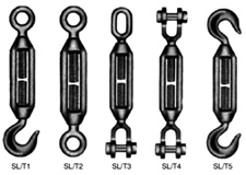
2 Products availableOur Complete range of products are Marzoli Peg, Electric Winches, Marzoli Rings, Crane Block and Straining Screws.

Multipurpose, Portable, Universal, Gearless, Handoperated Pulling and Lifting machine, Suppliedcomplete with telescopic, operating handle andstandard Length of super flex steel fibre-mixed corewire-rope fitted with Hook or Shackle at one end andfused and tapered at the other end
| Type | Normal Size | Length before Pressing Min. | Length after pressing Min | Thickness Min T | Suitable for Normal Wire Rope Size | |
| Lower Limit | Upper Limit | |||||
| (1) | (2) | (3) | (4) | (5) | (6) | (7) |
| Type A | 3 | 11 | 17 | 1.61 | 2.00 | 3.15 |
| 4.0 | 10 | 22 | 1.7 | 4.40 | 4.75 | |
| 6 | 10 | 23 | 2.1 | 5.85 | 6.30 | |
| 8 | 27 | 34 | 3.0 | 7.85 | 8.40 | |
| 9 | 30 | 33 | 3.50 | 8.80 | 9.45 | |
| 10 | 32 | 35 | 3.75 | 9.80 | 10.50 | |
| 11 | 36 | 43 | 5.25 | 10.75 | 11.55 | |
| Type B | 10 | 45 | 53 | 4.2 | 11.75 | 12.65 |
| 15 | 46 | 50 | 3.8 | 13.76 | 15.75 | |
| 17 | 50 | 60 | 5.2 | 15.76 | 17.85 | |
| 19 | 56 | 62 | 5.00 | 17.86 | 19.99 | |
| 21 | 62 | 70 | 6.20 | 20.00 | 21.99 | |
| 23 | 78 | 86 | 7.55 | 22.00 | 23.89 | |
| 25 | 83 | 94 | 8.00 | 24.00 | 25.99 | |
| 27 | 92 | 108 | 8.85 | 26.00 | 27.99 | |
| 29 | 98 | 114 | 9.85 | 28.00 | 29.00 | |
| 31 | 101 | 115 | 10.00 | 30.00 | 31.99 | |
| 33 | 105 | 118 | 11.07 | 32.00 | 33.99 | |

High quality spare parts for Marzoli machines manufacture, importers and suppliers in India.
We use the most advanced technology and graded raw materials to manufacture the Textile Machinery Marzoli Spare Parts like Marzoli Rings, Peg etc.
We have been regularly supplying this "Marzoli Spare Parts" to many contractors and associated people in this Field across India.
We would request to you to please send to us your enquiries for the same so that we can send to you more details and our commercial offer for the same.


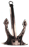
| Sole selling agent in India of Jiangsu Asian Star Anchor Chain Co. Ltd.for Anchors Chains |
| Chain Dia. | Grade2 | Grade3 | Approx. mass (27.5mm) | chain Dia | Grade2 | Grade3 | Approx. mass (27.5mm) | ||||
| Proof Load | Breaking Load | Proof Load | Breaking Load | Proof Load | Breaking Load | Proof Load | Breaking Load | ||||
| c=0.0098 | c=0.0137 | c=0.0137 | c=0.0196 | c=0.0098 | c=0.0137 | c=0.0137 | c=0.0196 | ||||
| mm | KN | KN | KN | KN | Kg | mm | KN | KN | KN | KN | Kg |
| 14 | 82 | 116 | 116 | 165 | 130 | 64 | 1560 | 2190 | 2190 | 3130 | 2529 |
| 16 | 107 | 150 | 150 | 216 | 170 | 66 | 1660 | 2310 | 2310 | 3300 | 2689 |
| 17.5 | 127 | 179 | 179 | 256 | 189 | 68 | 1750 | 2450 | 2450 | 3500 | 2858 |
| 19 | 150 | 211 | 211 | 301 | 226 | 70 | 1840 | 2580 | 2580 | 3690 | 3025 |
| 20.5 | 175 | 244 | 244 | 349 | 263 | 73 | 1990 | 2790 | 2790 | 3990 | 3341 |
| 22 | 200 | 280 | 280 | 401 | 303 | 76 | 2150 | 3010 | 3010 | 4300 | 3566 |
| 24 | 237 | 332 | 332 | 476 | 370 | 78 | 2260 | 3160 | 3160 | 4500 | 3756 |
| 26 | 278 | 389 | 389 | 556 | 439 | 81 | 2410 | 3380 | 3380 | 4820 | 4050 |
| 28 | 321 | 449 | 449 | 642 | 496 | 84 | 2580 | 3610 | 3610 | 5160 | 4355 |
| 30 | 368 | 514 | 514 | 735 | 564 | 87 | 2750 | 3850 | 3850 | 5500 | 4672 |
| 32 | 417 | 583 | 583 | 833 | 635 | 90 | 2920 | 4090 | 4090 | 5840 | 5000 |
| 34 | 468 | 655 | 655 | 937 | 724 | 92 | 3040 | 4260 | 4260 | 6080 | 5224 |
| 36 | 523 | 732 | 732 | 1050 | 812 | 95 | 3230 | 4510 | 4510 | 6440 | 5571 |
| 38 | 581 | 812 | 812 | 1160 | 905 | 97 | 3340 | 4680 | 4680 | 6690 | 5809 |
| 40 | 640 | 896 | 896 | 1280 | 1032 | 100 | 3530 | 4940 | 4940 | 7060 | 6174 |
| 42 | 703 | 981 | 981 | 1400 | 1075 | 102 | 3660 | 5120 | 5120 | 7320 | 6423 |
| 44 | 769 | 1080 | 1080 | 1540 | 1197 | 105 | 3850 | 5390 | 5390 | 7700 | 6806 |
| 46 | 837 | 1170 | 1170 | 1680 | 1310 | 107 | 3980 | 5570 | 5570 | 7960 | 7067 |
| 48 | 908 | 1270 | 1270 | 1810 | 1438 | 111 | 4250 | 5940 | 5940 | 8480 | 7606 |
| 50 | 981 | 1370 | 1370 | 1960 | 1536 | 114 | 4440 | 6230 | 6230 | 8890 | 8023 |
| 52 | 1060 | 1480 | 1480 | 2110 | 1669 | 117 | 4650 | 6510 | 6510 | 9300 | 8450 |
| 54 | 1140 | 1590 | 1590 | 2270 | 1780 | 120 | 4850 | 6810 | 6810 | 9720 | 8889 |
| 56 | 1220 | 1710 | 1710 | 2430 | 1936 | 122 | 5000 | 7000 | 7000 | 9990 | 9187 |
| 58 | 1290 | 1810 | 1810 | 2600 | 2086 | 124 | 5140 | 7200 | 7200 | 10280 | 9492 |
| 60 | 1380 | 1940 | 1940 | 2770 | 2249 | 127 | 5350 | 7490 | 7490 | 10710 | 9957 |
| 62 | 1470 | 2060 | 2060 | 2940 | 2373 | - | - | - | - | - | - |


| |||||||||||||||||||||||||
| Note | |||||||||||||||||||||||||
| |||||||||||||||||||||||||
| |||||||||||||||||||||||||
|


For intermediate sizes of wire ropes, the next larger size of bull dog grip shall be used.
|
Nominal Size |
Dia of Rope mm |
H1 | B |
C Dia |
D Dia |
E |
F Dia Min |
K Dia |
M |
Proof Load kn |
Safe Working Load kn |
|
|
Closed mm |
Open mm |
|||||||||||
| M12 | 8 | 330 | 525 | 230 | 27 | 10 | 4 | 20 | 12 | 177 | 10.0 | 5.0 |
| M16 | 10 | 370 | 550 | 230 | 27 | 10 | 4 | 22 | 12 | 197 | 18.0 | 9.0 |
| M20 | 12 | 400 | 570 | 230 | 34 | 10 | 4 | 25 | 16 | 211 | 28.0 | 14.0 |
| M24 | 14 | 475 | 700 | 300 | 34 | 12 | 5 | 32 | 16 | 246 | 36.0 | 18.0 |
| M27 | 16 | 550 | 825 | 360 | 43 | 12 | 5.5 | 35 | 20 | 290 | 44.0 | 22.0 |
| M30 | 18 | 550 | 825 | 360 | 43 | 14 | 5.5 | 38 | 20 | 290 | 63.0 | 31.5 |
| M33 | 20 | 600 | 875 | 380 | 48 | 14 | 6.5 | 44 | 25 | 325 | 75.0 | 37.5 |
| M36 | 22 | 600 | 875 | 380 | 60 | 16 | 6.5 | 47 | 25 | 325 | 86.0 | 43.0 |
| M39 | 25 | 660 | 960 | 400 | 60 | 16 | 6.5 | 50 | 25 | 350 | 100.0 | 50.0 |
| M45 | 29 | 700 | 960 | 400 | 76 | 19 | 6.5 | 60 | 28 | 378 | 112.0 | 56.0 |
| M52 | 32 | 750 | 1000 | 400 | 76 | 19 | 8 | 70 | 36 | 406 | 144.0 | 72.0 |
| M56 | 35 | 775 | 1025 | 400 | 83 | 19 | 8 | 73 | 36 | 421 | 194.0 | 97.0 |
| M60 | 38 | 800 | 1050 | 500 | 90 | 20 | 9.5 | 76 | 40 | 440 | 214.0 | 107.0 |
| M64 | 41 | 1070 | 1450 | 580 | 95 | 20 | 13 | 91 | 47 | 580 | 286.0 | 143.0 |
| M68 | 44 | 1120 | 1590 | 620 | 103 | 20 | 14 | 96 | 51 | 635 | 342.0 | 171.0 |
| M75 | 48 | 1270 | 1700 | 660 | 111 | 20 | 14 | 103 | 57 | 690 | 400.0 | 200.0 |
| M80 | 51 | 1360 | 1760 | 700 | 119 | 20 | 15 | 112 | 63 | 740 | 500.0 | 250.0 |
| M90 | 54 | 1440 | 1860 | 740 | 127 | 20 | 16 | 122 | 69 | 790 | 624.0 | 312.0 |

| ope Size |
Dimensions (mm) |
Min No. of Clamps |
Amt. of Rope to Turn Back in (cm)P |
||||||||
| (in.) | (mm) | A | B | C | D | E | F | G | H | ||
| 3/8 | 9-10 | 11.2 | 38.1 | 19.1 | 25.4 | 23.1 | 19.2 | 41.4 | 49.3 | 2 | 16.5 |
| 1/2 | 13 | 12.7 | 47.8 | 25.4 | 30.2 | 28.7 | 22.4 | 48.5 | 58.0 | 3 | 29.2 |
| 5/8 | 16 | 14.2 | 60.5 | 31.8 | 33.3 | 34.0 | 23.9 | 52.5 | 63.5 | 3 | 30.5 |
| 5/4 | 18-20 | 15.8 | 70.0 | 36.6 | 38.1 | 35.8 | 26.9 | 57.0 | 72.0 | 4 | 46 |
| 7/8 | 22 | 19.1 | 79.5 | 41.2 | 44.5 | 40.4 | 31.8 | 62.0 | 80.5 | 4 | 48 |
| 1 | 24-26 | 19.1 | 89.0 | 46.0 | 47.8 | 45.2 | 31.8 | 67.0 | 88.0 | 5 | 66 |
| 1 1/8 | 28-30 | 19.1 | 98.5 | 51.0 | 51.0 | 48.5 | 31.8 | 71.5 | 91.0 | 6 | 86 |
| 1 1/4 | 32-34 | 22.4 | 108 | 45.0 | 58.5 | 55.5 | 36.6 | 79.5 | 105 | 7 | 112 |
| 1 3/8 | 36 | 22.4 | 118 | 58.5 | 60.5 | 58.5 | 36.6 | 79.5 | 106 | 7 | 112 |
| 1 1/2 | 38-40 | 22.4 | 125 | 60.5 | 65.5 | 62.0 | 36.6 | 86.5 | 113 | 8 | 137 |
| 1 3/4 | 44-46 | 28.7 | 146 | 70.0 | 77.5 | 74.5 | 46.0 | 97.0 | 134 | 8 | 155 |
| 2 | 48-52 | 31.8 | 164 | 76.0 | 86.0 | 83.5 | 51.0 | 113 | 149 | 8 | 180 |

| Multipurpose, Portable, Universal, Gearless, Hand operated Pulling and Lifting machine, Supplied complete with telescopic, operating handle and standard Length of super flex steel fibre-mixed core wire-rope fitted with Hook or Shackle at one end and fused and tapered at the other end. |
| Pulling & Lifting Machines Hy-Tack XL Series 2005 |
| Technical Specifications | HT-7 | HT-13 | HT-20 | HT-35 | HT-58 |
| Dimensions (Approx.) | 515 x 265 x 110 | 600 x 360 x 155 | 620 x 360 x 155 | 720 x 400 x 160 | 810 x 465 x 190 |
| Capacity (SWL) (kgs) Lifting, Pulling | 750, 1250 | 1600, 2600 | 2000, 3000 | 3200, 5200 | 5000, 8000 |
| Length of Telescopic operating handle (Approx.) | 54/72 cm | 66/104 cm | 70/130 cm | 79/118 cm | 120/145 cm |
| Effort at full load (Approx.) kgs | 40 | 50 | 50 | 60 | 70 |
| Rope travel per Return stroke (Approx.) mm | 40 | 55 | 50 | 36 | 30 |
| Diameter of wire Rope (mm) | 8.0 | 11.3 | 12.0 | 16.3 | 20.0 |
| Standard Length with Each machine (meters) | 10 | 20 | 20 | 10 | 10 |
| breaking Load of wire rope (Approx.) | 4.5 Tons | 9.0 Tons | 10.0 Tons | 18.0 Tons | 24.0 Tons |


| |

| Features |
|

|

|
|
|
Push 500 | Push/Geared | Geared | Geared | |||
| Capacity | kg | 1000 | 3000 | 5000 | 10,000 | ||
| Inside of wheel flanges mm | Range 1 | 50-130 | 58-150 | 90-160 | 110-150 | 140-170 | |
| Range 2 | 140-200 | 150-210 | 160-220 | 160-210 | 180-210 | ||
| Range 3 | 210-305 | 210-305 | 220-305 | 215-265 | 215-245 | ||
| A Seat of susp, plate to runner tread | Range 1 & 2 mm | 75 | 89 | 110 | 84 | 137 | |
| Range 3 mm | 115 | 129 | 155 | ||||
| B runner tread diameter | mm | 50 | 65 | 90 | 175 | 225 | |
| C runner tread width | mm | 20 | 25 | 30 | 45 | 50 | |
| D runner centres | push mm | 70 | 90 | 125 | - | - | |
| Geared mm | - | 128 | 157 | 253 | 313 | ||
| E underside of runner to suspension plate | mm | 18 | 28 | 28 | - | - | |
| F underside of runners to top of hand chain wheel, geared travel only |
mm | 101 | 106 | 123 | - | - | |
| G beam flange to shaft end | mm | - | 124 | 124 | 180 | 275 | |

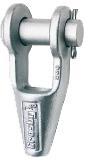
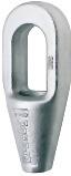
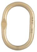
| Nominal Size of Rope |
A | B | C | D | E | F | G | H | J | K | L |
| (1) | (2) | (3) | (4) | (5) | (6) | (7) | (8) | (9) | (10) | (11) | (12) |
| 08 | 22 | 38 | 13 | 34 | 54 | 09 | 04 | 3.5 | 62 | 04 | 30 |
| 10 | 24 | 46 | 15 | 38 | 64 | 11 | 06 | 5.5 | 76 | 05 | 34 |
| 12 | 32 | 60 | 19 | 44 | 80 | 13 | 08 | 7.5 | 90 | 06 | 44 |
| 14 | 32 | 60 | 21 | 44 | 80 | 15 | 08 | 7.5 | 90 | 06 | 44 |
| 16 | 40 | 72 | 23 | 58 | 98 | 17 | 08 | 7.5 | 114 | 08 | 56 |
| 18 | 44 | 80 | 29 | 66 | 110 | 19 | 10 | 9.5 | 125 | 08 | 60 |
| 20 | 50 | 94 | 31 | 74 | 124 | 21 | 12 | 11.0 | 150 | 10 | 70 |
| 22 | 58 | 102 | 34 | 82 | 134 | 24 | 121 | 11.0 | 165 | 10 | 78 |
| 24 | 64 | 108 | 36 | 92 | 150 | 26 | 12 | 11.0 | 176 | 10 | 84 |
| 25 | 70 | 118 | 37 | 108 | 162 | 27 | 14 | 13.0 | 200 | 10 | 90 |
| 29 | 76 | 132 | 41 | 112 | 176 | 31 | 16 | 14.5 | 230 | 12 | 100 |
| 32 | 96 | 152 | 44 | 134 | 196 | 34 | 16 | 14.5 | 250 | 12 | 120 |
| 35 | 104 | 174 | 48 | 152 | 228 | 38 | 19 | 17.5 | 300 | 16 | 136 |
| 38 | 114 | 198 | 54 | 165 | 254 | 41 | 24 | 22.0 | 330 | 18 | 150 |
| 41 | 114 | 198 | 56 | 165 | 254 | 44 | 24 | 22.0 | 330 | 18 | 150 |
| 44 | 125 | 222 | 57 | 178 | 285 | 47 | 26 | 23.5 | 355 | 25 | 175 |
| 48 | 134 | 246 | 67 | 190 | 315 | 51 | 28 | 25.5 | 380 | 28 | 190 |
| 51 | 140 | 256 | 70 | 330 | 330 | 55 | 30 | 27.5 | 400 | 28 | 196 |
| 54 | 140 | 256 | 70 | 200 | 330 | 58 | 30 | 27.5 | 400 | 28 | 196 |
| 57 | 146 | 270 | 76 | 216 | 355 | 61 | 32 | 29.5 | 425 | 30 | 206 |
| 64 | 156 | 308 | 95 | 240 | 400 | 69 | 44 | 41.0 | 450 | 32 | 220 |
| 70 | 200 | 400 | 120 | 275 | 500 | 75 | 60 | 57.0 | 480 | 40 | 280 |

|
Working Load Limit (tons) |
Dimensions (mm) |
|||||||||||
| Carbon | Alloy | A | B | C | D | F | G | H | J | K | P | Q |
| 8 | 1.25 | 110 | 37.3 | 81.5 | 73.0 | 31.8 | 19.1 | 20.1 | 20.1 | 14.2 | 51.0 | 19.0 |
| 1 | 1.6 | 125 | 44.5 | 93.5 | 81.0 | 35.1 | 21.3 | 23.9 | 23.9 | 15.8 | 57.0 | 23.1 |
| 1.6 | 2.5 | 141 | 51.5 | 104 | 92.0 | 38.1 | 25.4 | 29.5 | 29.5 | 19.1 | 64.0 | 28.7 |
| 2 | 3.2 | 162 | 61.0 | 119 | 104 | 41.4 | 28.5 | 33.3 | 33.3 | 21.3 | 72.0 | 31.8 |
| 3.2 | 5.4 | 201 | 74.5 | 147 | 125 | 51.0 | 36.6 | 41.2 | 41.2 | 28.5 | 90.5 | 39.6 |
| 5 | 8 | 256 | 97.0 | 187 | 165 | 63.5 | 46.0 | 52.0 | 52.0 | 35.1 | 113 | 51.0 |
| 7.5 | 12.5 | 316 | 119 | 230 | 192 | 76.0 | 57.0 | 66.5 | 66.5 | 41.2 | 140 | 62.0 |
| 10 | 16 | 354 | 137 | 255 | 221 | 82.5 | 65.5 | 74.5 | 74.5 | 49.3 | 157 | 72.0 |
| 15 | 22 | 434 | 168 | 318 | 279 | 108 | 75.5 | 89.0 | 89.0 | 60.5 | 186 | 89.0 |
| 20 | 30 | 495 | 178 | 357 | 346 | 127 | 92.0 | 117 | 117 | 76.0 | 223 | 89.0 |
| 25 | 37 | 630 | 216 | 462 | 357 | 137 | 116 | 127 | 127 | 92.0 | 289 | 114 |
| 30 | 45 | 697 | 236 | 511 | 392 | 152 | 129 | 140 | 140 | 94.5 | 321 | 125 |
| 40 | 60 | 821 | 273 | 602 | 470 | 178 | 152 | 165 | 165 | 113 | 376 | 145 |

Bolt type anchor shackles with thin head bolt-nut with cotter pin. Meets the requirements of Federal Specification
Features
| Working Load Limit Tonnes ISS Crosby |
Body Dia d C (mm) |
Pin Dia D B (mm) |
Jaw Inside Width (W) A (mm) |
Bow Dia (F) (mm) |
Inside Length C (mm) |
Eye Outside Dia (E) (mm) |
Average Weight with Nut Bolt Type Pin (kg) |
| 0.33 | 4.8 | 6.4 | 9.7 | 15.2 | 22.3 | 14.2 | 0.0 |
| 0.5 | 6.4 | 7.9 | 11.9 | 19.8 | 28.7 | 15.5 | 0.1 |
| 0.75 | 7.9 | 9.7 | 13.5 | 21.3 | 30.9 | 19.1 | 0.1 |
| 1.0 | 9.7 | 11.2 | 16.8 | 26.1 | 36.5 | 23.1 | 0.1 |
| 1.5 | 11.2 | 12.7 | 19.1 | 28.7 | 42.9 | 26.9 | 0.2 |
| 2.0 | 12.7 | 16.0 | 20.6 | 33.3 | 47.7 | 30.2 | 0.3 |
| 3.25 | 16.0 | 19.1 | 26.9 | 42.9 | 60.5 | 38.1 | 0.6 |
| 4.75 | 19.1 | 22.4 | 31.8 | 51.0 | 71.0 | 46.0 | 1.0 |
| 6.5 | 22.4 | 25.4 | 36.6 | 58.0 | 84.0 | 53.0 | 1.5 |
| 8.5 | 25.4 | 28.7 | 42.9 | 68.5 | 95.0 | 60.5 | 2.4 |
| 9.5 | 28.7 | 31.8 | 46.0 | 74.0 | 108.0 | 68.5 | 3.1 |
| 12.0 | 31.8 | 35.1 | 51.5 | 82.5 | 119.0 | 76.0 | 4.3 |
| 13.5 | 35.1 | 38.1 | 57.0 | 92.0 | 133.0 | 85.0 | 6.0 |
| 17.0 | 38.1 | 41.4 | 60.5 | 98.5 | 146.0 | 92.0 | 7.8 |
| 25.0 | 44.5 | 51.0 | 73.0 | 127.0 | 178.0 | 106.0 | 13.8 |
| 35.0 | 51.0 | 57.0 | 82.5 | 146.0 | 197.0 | 122.0 | 20.4 |
| 55.0 | 66.5 | 70.0 | 105.0 | 184.0 | 267.0 | 145.0 | 38.9 |
| 85.0 | 76.0 | 82.5 | 127.0 | 200.0 | 330.0 | 165.0 | 70.0 |
| 120.0 | 92.0 | 95.0 | 133.0 | 229 | 372.0 | 203.0 | 120.0 |
| 150.0 | 104.0 | 108.0 | 140.0 | 254.0 | 368.0 | 229.0 | 153.0 |

|

| All dimensions in mmProof Load = 2 x S.W.L. (Safe Working Load)Other threads can also be supplied to special order. | |||||||
| |||||||
| Forged Eye Bolt Warning & Applications | |||||||
| Important Safety Information - Read & Follow | |||||||
| Inspection / Maintenance Safety | |||||||
| Never use eye bolt that shows signs of wear or damage | |||||||
| Never use eye bolt if eye or shank is bent or elongated. | |||||||
| Always be sure threads on shank and receiving holes are clean | |||||||
| Never machine, grind, or cut eye bolt. | |||||||
| Assembly Safety | |||||||
| Never exceed load limits specified in Table I | |||||||
| Never use regular nut eye bolts for angular lifts. | |||||||
| Always use shoulder nut eye bolts (or machinery eye bolts) for angular lifts. | |||||||
| For angular lifts, adjust working load as follows: | |||||||
| Never undercut an eye bolt to seat shoulder against the load. | |||||||
| Always countersink receiving hole or use washers to seat shoulder. | |||||||
| Always screw eye bolt down completely for proper seating. | |||||||
| Always tighten nuts securely against the load. | |||||||
| Shoulder Nut Eye Bolt - Installation for Angular loading | |||||||
| Operating Safety | |||||||
| Always stand clear of load | |||||||
| Never lift load with steady, even pull - do not jerk. | |||||||
| Always apply load to eye bolt in the plane of the eye, not at an angle | |||||||
| Never exceed the capacity of the eye bolt. | |||||||
| When using lifting slings of two or more legs, make sure the loads in the legs are calculated using the angle from the vertical to the leg and properly size the shoulder nut or machinery eye bolt for the angular load. | |||||||
| Warnings | |||||||
| Loads may slip or fall if proper eye bolt assembly and lifting procedures are not used. | |||||||
| A falling load can seriously injure or kill. Read, & understand all instructions and diagrams. Follow all eye bolt safety information provided here. | |||||||
| S.W.L. at 0o kg | Size Dia. A | Coarse Pitch | B | D | E | F | G | H | M |
Approx Wt. each kg. |
| 85 | 8 | 1.25 | 20 | 6 | 20 | 8 | 18 | 12 | 10 | 0.06 |
| 150 | 10 | 1.50 | 25 | 8 | 25 | 10 | 22 | 18 | 12 | 0.11 |
| 220 | 12 | 1.75 | 30 | 10 | 30 | 12 | 26 | 22 | 14 | 0.18 |
| 380 | 16 | 2.00 | 35 | 12 | 35 | 14 | 30 | 28 | 16 | 0.28 |
| 570 | 20 | 2.50 | 40 | 14 | 40 | 16 | 35 | 30 | 19 | 0.44 |
| 810 | 22 | 2.50 | 45 | 16 | 45 | 18 | 40 | 35 | 21 | 0.55 |
| 1050 | 24 | 3.00 | 50 | 18 | 50 | 20 | 45 | 38 | 24 | 0.74 |
| 1700 | 30 | 3.50 | 65 | 22 | 60 | 24 | 55 | 45 | 28 | 1.66 |
| 2500 | 36 | 4.00 | 75 | 26 | 70 | 28 | 65 | 55 | 32 | 2.7 |
| 3400 | 42 | 4.50 | 85 | 30 | 80 | 32 | 75 | 65 | 38 | 4.0 |
| 5200 | 48 | 5.00 | 100 | 35 | 90 | 38 | 85 | 70 | 46 | 6.4 |
| 6500 | 56 | 5.50 | 110 | 38 | 100 | 42 | 95 | 80 | 50 | 8.8 |
| 8700 | 64 | - | 120 | 42 | 110 | 48 | 105 | 90 | 58 | - |
| 13000 | 72 | - | 150 | 50 | 140 | 60 | 130 | 105 | 72 | - |
| 17000 | 80 | - | 170 | 55 | 160 | 68 | 150 | 120 | 80 | - |
| 20000 | 100 | - | 190 | 60 | 180 | 75 | 165 | 130 | 88 | - |

| S.W.L. on Hook tons | No of Sheaves |
A mm |
B mm |
For Dia. Wire Rope mm |
D mm |
± L mm |
E mm |
F mm |
R mm |
Approx. Wt. per Pc kg |
| 10 | 1 | 350 | 300 | 20 | 55 | 720 | 33 | 30 | 35 | 175 |
| 13 | 1 | 350 | 300 | 20 | 70 | 790 | 39 | 35 | 40 | 190 |
| 17 | 1 | 450 | 400 | 22 | 75 | 960 | 48 | 40 | 50 | 210 |
| 12 | 2 | 300 | 250 | 18 | 40 | 750 | 30 | 28 | 30 | 130 |
| 12 | 2 | 350 | 300 | 20 | 40 | 800 | 30 | 28 | 30 | 170 |
| 27 | 2 | 400 | 250 | 22 | 70 | 1060 | 42 | 40 | 42 | 220 |
| 27 | 2 | 450 | 400 | 22 | 70 | 1110 | 42 | 40 | 42 | 260 |
| 35 | 2 | 450 | 400 | 22 | 80 | 1220 | 48 | 45 | 50 | 280 |
| 15 | 3 | 300 | 250 | 18 | 45 | 750 | 30 | 25 | 30 | 145 |
| 18 | 3 | 350 | 300 | 20 | 50 | 850 | 30 | 28 | 30 | 190 |
| 30 | 3 | 400 | 350 | 22 | 60 | 1050 | 39 | 35 | 40 | 315 |
| 35 | 3 | 400 | 350 | 22 | 70 | 1125 | 39 | 35 | 40 | 315 |
| 20 | 4 | 350 | 300 | 20 | 55 | 870 | 30 | 28 | 30 | 290 |
| 27 | 4 | 350 | 300 | 20 | 55 | 980 | 30 | 28 | 30 | 290 |
| 32 | 4 | 350 | 300 | 20 | 60 | 1075 | 33 | 30 | 33 | 310 |
| 45 | 4 | 450 | 400 | 22 | 70 | 1300 | 40 | 35 | 40 | 475 |
| 45 | 4 | 500 | 450 | 26 | 70 | 1300 | 40 | 35 | 40 | 500 |

| Features | |
|

| ||||||
|