Our Products
Electronic Components
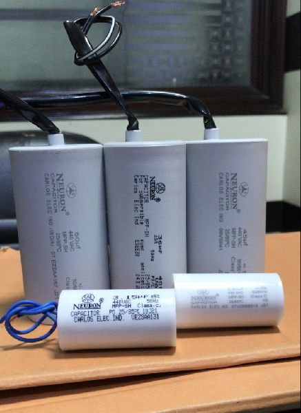
1 Products availableWe offer the best product range of Fan Capacitor, 4.0 mfd Capacitor, Power Capacitor, oil filled electrical capacitor and Oil Filled Capacitor.

Selection Guide For Capacitor : Review following factors when selecting capacitors for any given application.
nSpecification
| Capacitance Value (µF) |
Tolerance | Dimensions (± 2. Omm) Ø x H (mm x mm) |
|---|---|---|
| 1.50-2.50 | ±5% | 28 x 54 |
| 3.00-4.00 | ±5% | 30 x 54 |
| 4.00-5.00 | ±5% | 35 x 54 |
| 6.00-8.00 | ±5% | 35 x 70 |
| 10 | ±5% | 40 x 70 |
Note :

We are the main supplier of this product.

Energy conservation has become a central issue of utmost priority all over the world today. Power being a major of expenditure in industries, it is equally important conserve power to maximum to sustain in competition of industrial goods. This can be done only by best utilization of available capacity of cables, switchgears & transformers, line losses, by reducing reactive current. The main source of reactive currents are inductive load, such as fan, indication motors, transformers, welding sets, fluorescent & gas lamps. Such kind of equipments draw not only active power (KW), but also reactive power (KVAR), from the supply. this reactive power is necessary for the equipment to operate correctly, could be interpreted as an undesirable burden on the supply. The vector total of these two is apparent power (KVA). P.F.(cos) = KW/KVA (The closer cos is to unity the less reactive power is drawn from the supply.
nnRole of Power Capacitor in P.F.C. :
n
Application :
Construction : power capacitors and manufactured in perfectily dust free controlled environment using latest technologies and processes to ensure most reliable performance and impeccable long life in service. Use of high quality reinforced edge, zinc alloy MPP film on automated winding machines ensures good element winding. Material selection at every process is made judiciously towards this end.
Testings : Works is equipped with latest test laboratory where all kinds of routine test, type can be carried out as per Indian & international standard. This in house facility is used for ensuring reliability before release and development of new design, inputs processes.
Wide Range of Power Capacitor :
Silent Features :
Information to be given with enquiry or order :
Electrical Characteristices
| Electrical Characteristices | SH Normal Duty | SH OIL Type | Double Dielectric Heavy Duty |
|---|---|---|---|
| Max. Permissble Voltage | 1.1 Un | 1.2 Un | 1.3 Un |
| Max. Permissible Current | 1.3 In | 1.4 In | 1.5 In |
| Max. Permissble transient peak current | 100 In | 200 In | 200 In |
| Losses (Total) Per KVAR | < 0.5W / kvar | < 0.5W / kvar | < 0.5W/ kvar |
| Designed for | Linear inductive load | Non linear induct. load uoto 10% | Non Linear induct load upto 15% |
Table For Determining Power Capactor Rating For Direct Connection To Induction Motors :
| CAPACITOR RATING (KVAR) WHEN MOTOR SPEED (R.P.M) is | ||||||
|---|---|---|---|---|---|---|
| Motor H.P. | 3500 | 3000 | 1000 | 750 | 600 | 500 |
| 2.5 | 1 | 1 | 1.5 | 2 | 2.5 | 2.5 |
| 5 | 2 | 2 | 2.5 | 3.5 | 4 | 4 |
| 7.5 | 3 | 2.5 | 3.5 | 4.5 | 5 | 5.5 |
| 10 | 4 | 3 | 4.5 | 5.5 | 6 | 65 |
| 15 | 5 | 4 | 6 | 7.5 | 8.5 | 9 |
| 20 | 6 | 5 | 7 | 9 | 11 | 12 |
| 25 | 7 | 6 | 9 | 10.5 | 13 | 14.5 |
| 30 | 8 | 7 | 10 | 12 | 15 | 17 |
| 40 | 10 | 9 | 13 | 15 | 19 | 21 |
| 50 | 12.5 | 11 | 16 | 18 | 23 | 25 |
| 60 | 14.5 | 13 | 18 | 20 | 26 | 28 |
| 70 | 16.5 | 15 | 20 | 22 | 28 | 31 |
| 80 | 19 | 17 | 22 | 24 | 30 | 34 |
| 90 | 21 | 19 | 24 | 26 | 33 | 37 |
| 100 | 23 | 21 | 26 | 28 | 35 | 40 |
| 110 | 25 | 23 | 28 | 30 | 38 | 43 |
| 120 | 27 | 25 | 30 | 32 | 40 | 46 |
| 130 | 29 | 27 | 32 | 34 | 43 | 48 |
| 150 | 33 | 31 | 36 | 38 | 48 | 55 |
| 160 | 35 | 33 | 38 | 40 | 50 | 57 |
| 190 | 40 | 38 | 43 | 45 | 58 | 65 |
| 200 | 42 | 40 | 45 | 47 | 60 | 67 |
Note : The recommended Capacitor ratings shown in the table are for improving the power factor to 0.95, and these values are for guidance only.
Table For Determing Power Capacitor Rating :
| DESIRED POWER FACTOR | ||||||||
|---|---|---|---|---|---|---|---|---|
| Existing Power Factor | 0.850 | 0.90 | 0.95 | 0.96 | 0.97 | 0.98 | 0.99 | 1.0 |
| 0.40 | 1.668 | 1.805 | 1.959 | 1.998 | 2.037 | 2.085 | 2.146 | 2.288 |
| 0.50 | 1.112 | 1.248 | 1.403 | 1.441 | 1.481 | 1.528 | 1.590 | 1.732 |
| 0.60 | 0.714 | 0.849 | 1.005 | 1.043 | 1.083 | 1.131 | 1.192 | 1.334 |
| 0.65 | 0.549 | 0.685 | 0.840 | 0.878 | 0.918 | 0.966 | 1.027 | 1.169 |
| 0.67 | 0.488 | 0.624 | 0.779 | 0.817 | 0.857 | 0.905 | 0.966 | 1.108 |
| 0.68 | 0.459 | 0.595 | 0.750 | 0.788 | 0.828 | 0.876 | 0.937 | 1.079 |
| 0.69 | 0.429 | 0.565 | 0.720 | 0.758 | 0.798 | 0.840 | 0.907 | 1.049 |
| 0.70 | 0.400 | 0.536 | 0.691 | 0.729 | 0.741 | 0.811 | 0.878 | 1.020 |
| 0.71 | 0.372 | 0.508 | 0.663 | 0.701 | 0.712 | 0.783 | 0.850 | 0.992 |
| 0.72 | 0.343 | 0.479 | 0.634 | 0.672 | 0.685 | 0.754 | 0.821 | 0.963 |
| 0.73 | 0.316 | 0.452 | 0.607 | 0.645 | 0.658 | 0.727 | 0.794 | 0.936 |
| 0.74 | 0.289 | 0.425 | 0.580 | 0.618 | 0.631 | 0.700 | 0.767 | 0.909 |
| 0.75 | 0.262 | 0.398 | 0.553 | 0.591 | 0.604 | 0.673 | 0.740 | 0.882 |
| 0.76 | 0.235 | 0.371 | 0.526 | 0.564 | 0.578 | 0.652 | 0.713 | 0.855 |
| 0.77 | 0.209 | 0.345 | 0.500 | 0.538 | 0.552 | 0.620 | 0.687 | 0.829 |
| 0.78 | 0.183 | 0.319 | 0.474 | 0.512 | 0.525 | 0.594 | 0.661 | 0.808 |
| 0.79 | 0.156 | 0.292 | 0.447 | 0.485 | 0.499 | 0.567 | 0.635 | 0.776 |
| 0.80 | 0.130 | 0.266 | 0.421 | 0.459 | 0.473 | 0.541 | 0.608 | 0.750 |
| 0.81 | 0.104 | 0.240 | 0.395 | 0.433 | 0.447 | 0.515 | 0.582 | 0.724 |
| 0.82 | 0.078 | 0.214 | 0.369 | 0.407 | 0.421 | 0.489 | 0.556 | 0.698 |
| 0.83 | 0.052 | 0.118 | 0.343 | 0.381 | 0.395 | 0.463 | 0.530 | 0.672 |
| 0.84 | 0.026 | 0.162 | 0.317 | 0.355 | 0.367 | 0.437 | 0.504 | 0.645 |
| 0.85 | --- | 0.136 | 0.291 | 0.329 | 0.377 | 0.417 | 0.478 | 0.620 |
| 0.87 | --- | 0.083 | 0.238 | 0.275 | 0.317 | 0.364 | 0.424 | 0.567 |
| 0.90 | --- | --- | 0.155 | 0.192 | 0.234 | 0.281 | 0.341 | 0.484 |
| 0.95 | --- | --- | --- | 0.037 | 0.078 | 0.126 | 0.186 | 0.329 |
Example : For the given load of 50 H.P., corresponding KW= 50 X 0.746 = 37.3 Existing P.F. = 0.80
Desired P.F = 0.95 From The row & column of the table, obtain Multiplying Factor = 0.421 Power Capacitor (KVAR) = 37.3 X 0.421 =15.7 Power Capacitor of 15 KVAR should be selected


Selection Guide For Capacitor : Review following factors when selecting capacitors for any given application.
nn

Selection Guide For Capacitor : Review following factors when selecting capacitors for any given application.
nSpecification
| Dimensions (± 2.0mm_ ) ¢ x mm | ||
|---|---|---|
| Capacitanec Value (µF) |
Dry | Oil filled |
| IS:2993-1998 | ||
| 1.0-2.50 | ractangular 40x20x30 | |
| 1.50-3.15 | 25x52Clamp | ---- |
| 1.50-2.50 | 28x52 | 28x54 |
| 3.00-4.00 | 30x52 | 30x54 |
| 4.00-6.00 | 34x52 | 35x54/72 |
| 6.00-10.0 | 34x70 | 35x72 |
| 10.0-15.0 | 40x70 | 40x72 |
| 20.0-36.0 | 40/45x95 | 45x95 |
| 36.0-50.0 | 45x125 | 50x125 |
| 2.1+5.30, 3.5+7.00 | 40x95 | ---- |
| 4.0+8.0,6.0+9.0 | 40X125 | ---- |
| 2.5+10.0, 5.0+10.0 | 40X125 | ---- |
| 6.0+12.0, 4.0+36.0 | 45X125 | ---- |
| 72.0, 108.0, 144.0 | M.S. Flat Boxe | ---- |
| 180.0, 216.0µ | M.S. Flat Boxe | ---- |

Selection Guide For Capacitor : Review following factors when selecting capacitors for any given application.
nIS: 2993 Motor Start Cap.
| Capacitance Value (µF) | Rated Volt. | Dimensions (± 2. Omm) Ø x H (mm x mm) | Application |
|---|---|---|---|
| 30 – 40 | 250 | 40 X 70 | 0.25 F.H.P Motors |
| 40 – 60 | 250 | 40/45 X 70 | 0.33 F.H.P Motors |
| 60 – 80 | 250 | 40/45 X 95 | 0.5 F.H.P Motors |
| 80 – 100 | 250 | 40/45 X 95 | 0.75 F.H.P Motors |
| 100 – 120 | 250 | 45 X 95/125 | 1.0 F.H.P Motors |
| 120 – 150 | 250 | 45/50 X 125 | 1.5 F.H.P Motors |
| 150 – 200 | 250 | 45/50 X 125 | 2.0 F.H.P Motors |
| 200 – 250 | 250 | 45/50 X 125 | 0.10 F.H.P Motors |

selection guide for capacitor : review following factors when selecting capacitors for any given application.
nSpecification
| Capacitance Value (µF) | Rated Volt. | Dimensions (± 2. Omm) Ø x H (mm x mm) | Application |
|---|---|---|---|
| IS: 1569-1976 | 40W - 2 Nos. of FTL | ||
| 3.15 | 400V AC | 28 X 52 | 65W - 1 No. of FTL |
| 4.00 | 250V AC | 28 X 52 | 40W - 1 No. of FTL |
| 8 | 250V AC | 30/35 X 52 | 80 W - 1 No. of HPMV |
| 10 | 250V AC | 35 X 52 | 125W - 1 No. of HPMV |
| 15 | 250V AC | 35 X 70 | 70W - 1 No. of HPSV |
| 20 | 250V AC | 40 X 70 | 250W - 1 No. of HPMV |
| 33 | 250V AC | 40/45 X 95 | 400W - 1 No. of HPMV |
| 42 | 250V AC | 40/45 X 95 | 150W - 1 No. HPMV |
| ----- | ----- | ----- | 250W - 1 No. of HPSV |

Selection Guide For Capacitor :Review following factors when selecting capacitors for any given application.
n
selection guide for capacitor :review following factors when selecting capacitors for any given application.
n