Welcome to Bhartiya Group India
Manufacturer / Exporter / Supplier / Retailer Of gas plant, industrial gas plant, Natural Gas Plant, nitrogen gas plant, liquid plants, Oxygen Plant, CYROGENIC LIQUID PLANT, Acetylene Plant, nitrous oxide plant
Welcome to Bhartiya Group India
Manufacturer / Exporter / Supplier / Retailer Of gas plant, industrial gas plant, Natural Gas Plant, nitrogen gas plant, liquid plants, Oxygen Plant, CYROGENIC LIQUID PLANT, Acetylene Plant, nitrous oxide plant

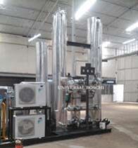
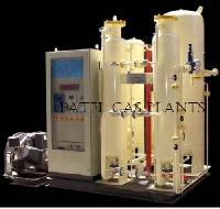
Suction Filter High efficiency filter supplied with the compressor Air Compressor: This is a multistage heavy duty water cooled air compressor with fly wheel inter cooler, foundation bolts, motor pulley, v belt, guard and slide rails and air filter. This is used to compress atmospheric air complete with motor and Starter. Process Skid (Skid Mounted Version): Consisting of the following 1. After cooler with tank 2. Nitrogen cooler with tank 3. Moisture separator 4. Chilling unit with freon unit 5. Oil absorber filled with alumina 6. Molecular sieve battery on skid 7. Defrost heater 8. Gas/Air/water line as per standard layout on skid/ /platform prefabricated and ready for installation. 9. Water pump. 10. Inlet & outlet water lines 11. Drain manifold complete with ball valves for draining moisture copper pipes (inlet and outlet) hydraulically operated high efficient engine with ball type of valves stainless steel liner vertical type of German Design. Expansion Engine with Motor: Complete with motor and starter with hydraulic valve control, bursting disc for safety, complete with flywheel pressure gauge, motor pulley v belt, belt guard, slide rails inter connected MANUFACTURING PROCESS 1. COMPRESSION OF ATMOSPHERIC AIR BY AIR COMPRESSOR The free saturated air is sucked from atmosphere through a highly efficient dry-type suction filter into the first stage of the horizontal balanced opposed, lubricated reciprocating air compressor. Compresssed air is chilled to 12 degree centigrade in a chilling unit ata temperature of 12 degree centigrade to a moisture separator where the condensed moisture gets removed before entering into Molecular Sieve Battery. Before sending the air to MOLECULAR SIEVE BATTERY, air is passed through an OIL ABSORBER where air becomes oil free. 2. PURIFICATION OF AIR BY PROCESS SKID Chilled air passes through the Molecular Sieve Battery consisting of Twin Tower packed with Molecular Sieves to remove moisture and Carbon dioxide present in the air. Molecular Sieve Battery operates on Twin Tower System, when one tower is under production the other tower is regenerated by passing waste Nitrogen gas at 200 degC through a reactivation heater. After interval of 8 to 10 hours, the tower under production gets exhausted and regenerated by similar process before use and thus the cycle continues. Any dust particles gets filtered in the DUST FILTER before air enters the AIR SEPARATION COLUMN. 3. COOLING OF AIR BY EXPANSION ENGINE (EXPANDER) The process air before liquefication in the air separation unit needs to be cooled to temperatures sub-zero (cryogenic). The main portion of the air after the process skid enters the expansion engine through the heat exchanger no. I after pre-cooling. The temperature of the air drops to around -165degC by the Expander which is a very highly efficient advanced design with Teflon piston rings and completely hydraulic mechanism with leakproof ball valves. 4. SEPARATION IF LIQUID AIR INTO OXYGEN AND NITROGEN BY AIR SEPARATION COLUMN Chilled, Oil free and moisture free air enters into multi-pass HEAT EXCHANGER NO.I where it gets cooled to (-80) degC by cold gained from outgoing waste Nitrogen and Oxygen. A part of air this enters a multi-pass HEAT EXCHANGER NO. II or LIQUIFIER made of special Alloy tubes. This air cools to (-170) degC before passing through an expansion valve. Due to joule Thompson Effect, after the expansion valve. Due to joule Thompson Effect, after the expansion valve, air gets further cooled down and gets liquified before entering into bottom column is known as rich liquid. The rich liquid in the bottom column enters into feed tray of top column enters into feed tray of top column. Similarly the liquid nitrogen called POOR LIQUID enters into top column as a reflux & it takes away the latest heat of condensing Oxygen and gets vapourised whereas the liquid Oxygen flows down the trays of the top column into the Condenser passes through a Sub-Cooler to a LO Pump. 5. COMPRESSION/WITHDRAWAL AND FILLING OF OXYGEN AND NITROGEN Liquid oxygen pump pumps Liquid Oxygen through heat exchanger no. II and I, where liquid Oxygen gets gasified before filling in Cylinders in the Filling Manifold. The pure bone dry Oxygen gas at ambient temperature and high pressure is filled into Oxygen Cylinders through manifold valves by means of the highly efficient reciprocating LO pump.

The output of liquid oxygen can be stored in a liquid oxygen tank. Liquid Nitrogen can be available as a by product simultaneously upto 99.999% (PPM GRADE) purity. The plant is extremely versatile and all the possible product variants are possible you can either take 100% Liquid oxygen out put or 50% Liquid oxygen output directly into cylinders or 50% Liquid oxygen and 50% Liquid nitrogen. MANUFACTURING PROCESS 1. COMPRESSION OF ATMOSPHERIC AIR BY AIR COMPRESSOR The free saturated air is sucked from atmosphere through a highly efficient dry-type suction filter into the first stage of the horizontal balanced opposed, lubricated reciprocating air compressor. Compresssed air is chilled to 12 degree centigrade in a chilling unit ata temperature of 12 degree centigrade to a moisture separator where the condensed moisture gets removed before entering into Molecular Sieve Battery. Before sending the air to MOLECULAR SIEVE BATTERY, air is passed through an OIL ABSORBER where air becomes oil free. 2. PURIFICATION OF AIR BY PROCESS SKID Chilled air passes through the Molecular Sieve Battery consisting of Twin Tower packed with Molecular Sieves to remove moisture and Carbon dioxide present in the air. Molecular Sieve Battery operates on Twin Tower System, when one tower is under production the other tower is regenerated by passing waste Nitrogen gas at 200 degC through a reactivation heater. After interval of 8 to 10 hours, the tower under production gets exhausted and regenerated by similar process before use and thus the cycle continues. Any dust particles gets filtered in the DUST FILTER before air enters the AIR SEPARATION COLUMN. 3. COOLING OF AIR BY EXPANSION ENGINE (EXPANDER) The process air before liquefication in the air separation unit needs to be cooled to temperatures sub-zero (cryogenic). The main portion of the air after the process skid enters the expansion engine through the heat exchanger no. I after pre-cooling. The temperature of the air drops to around -165degC by the Expander which is a very highly efficient advanced design with Teflon piston rings and completely hydraulic mechanism with leakproof ball valves. 4. SEPARATION IF LIQUID AIR INTO OXYGEN AND NITROGEN BY AIR SEPARATION COLUMN Chilled, Oil free and moisture free air enters into multi-pass HEAT EXCHANGER NO.I where it gets cooled to (-80) degC by cold gained from outgoing waste Nitrogen and Oxygen. A part of air this enters a multi-pass HEAT EXCHANGER NO. II or LIQUIFIER made of special Alloy tubes. This air cools to (-170) degC before passing through an expansion valve. Due to joule Thompson Effect, after the expansion valve. Due to joule Thompson Effect, after the expansion valve, air gets further cooled down and gets liquified before entering into bottom column is known as rich liquid. The rich liquid in the bottom column enters into feed tray of top column enters into feed tray of top column. Similarly the liquid nitrogen called POOR LIQUID enters into top column as a reflux & it takes away the latest heat of condensing Oxygen and gets vapourised whereas the liquid Oxygen flows down the trays of the top column into the Condenser passes through a Sub-Cooler to a LO Pump. 5. WITHDRAWAL LIQUID OXYGEN AND STORAGE IN STORAGE TANK The final product from a liquid Oxygen/Nitrogen goes to the storage tank.


MANUFACTURING PROCESS Salient Features: No bulky gas holder required Automatic Controls for feeding water. Maintaining temperatures, pressures, and slurry drain are full proof, efficient and are of international standard. Excellent absorption of gas in cylinders No gas loss and high yield. Very simple and safe to operate Lower power consumption Low maintenance cost. Acetylene Generator Our Acetylene generator is a fully automatic plant. Pneumatically controlled valves and highly sensitive sensors, integral with the temperature control instruments, perform all operations. These in turn open the water inlet valve or residue drain valve etc. Two hydraulic pumps help to open and close the supply of calcium carbide, which is fed into the generator by screw feed conveyors. The screw feed mechanism and the agitators are operated by flameproof motors and fittings. The entire operation is perfectly synchronized to give maximum efficiency and simplicity in operation. Any failure, whether it is of power supply, water or air is signaled visually and also audibly when an alarm bell rings to alert the operator. Chemical Purifier This consists of two layers of regenerative chemicals, which remove additional impurities. The purifying agent may be reactivated for re-use by the atmosphere air. For continuous operation one extra charge of chemicals can be kept in open wooden trolley. Water Scrubber The equipment is installed between the chemical purifier and the high-pressure compressor which helps to remove additional impurities from the gas if any Acetylene Compressor The acetylene compressor is a three stage machine which is immersed in water filled tank to avoid any pressurized gas to come in contact with air and also to make sure that all the components are continuously cooled. The compressor is drawn by flame proof motor from outside the tank. No Loss Carbide Charge No gas is lost or wasted while charging the carbide because that section is completely sealed off from the generator by a high pressure hydraulically operated valve. All the above controls are automatic and require no attention from the operator. There is a further safety device, in terms of an alarm bell, which will ring continuously till the fault is corrected High Pressure Drier This consists of a battery of three high-pressure vessels. The first is filled with metal filler, while the second and third are filled with anhydrous calcium chloride. It is very important that the high pressure drier is fully filled up with Calcium Chloride, as any voids in high- pressure area are against the required safety Filling Manifold The acetylene gas manifold consists of two headers fitted with non-return valves, one flash back arrestors, pressure gauge and manual isolation valves. Instrument Air Compressor A flameproof motor with a buffer tank drives the instrument air compressor Acetone Pump Acetone pump is supplied along with the plant for charging acetone in cylinders Level Controls Level controller maintaining a particular level in the generator. If the level is above normal, water can enter the carbide hop Level Alarm The pressure inside the acetylene generator is controlled by a meteoroid switch Pressure Alarm This is the important part for the safety of this plant. A pressure switch is connected to the alarm system

Share your thoughts with other customers for Bhartiya Group India
Add Review