Our Products
Trolleys
1 Products availableSeparators & Strainers
1 Products availableWe offer a complete product range of Electromagnetic Flow Meter, Clamp on Ultrasonic Flow Meter, Ultrasonic Flow Meter, Multi Jet Class B AMR Water Meter and AMR Compatible Multi Jet Class B Water Meter

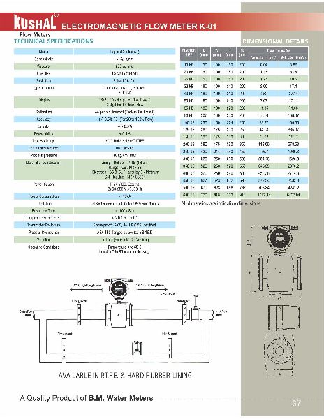
K-01 are micro-controller full bore electromagnetic flow transmitter specially used for various industrial applications. These flow transmitters accurately measures the flow rate of conductive liquids of slurries in closed pipes. Due to simple & rigid design, the flow transmitter in an obstruction less & maintenance free instrument in place of conventional mechanical flow measuring device. The use of 'Pulsed DC' technology offers highest ability & better measuring accuracy in the form of electrical signal 4-20 mA DC linearly proportional to volumetric flow. The instrument is based on Faraday's law of electro-magnetic field generates a voltage that is proportional to the flow velocity. Corresponding electrical output is provided with respect to measuring voltage.
nnSalient Features :
nGraph
Technical Details
| Media | Liquid (conductive) |
|---|---|
| Conductivity | >5 u s/cm |
| Viscosity | 200 CP Max |
| Line size | 15 NB TO 600 NB |
| Excitation | Pulsed DC Coil |
| Type OF output | 1) 4 to 20 mA DC, Isolated 2) Pulse |
| Display | 16x2 LCD – 4 Digit for flow rate & 8 digit for totailsed Flow |
| Callibration | As Per requirement (Factory Callibrated) |
| Accuracy | :+/- 0.5 % (for 20 to 100% flow) |
| Linerlity | +/- 0.5 % |
| repeatability | +/- 1% |
| Process Temp. | 70 oc Rubber/ 150 oc PTFE |
| Communication Port | On Demand |
| Process Pressure | 10 kg/cm2 max |
| Materlal Of construction | Lining – rubber/ PTFE (Telfon), Flange – CS/MS/SS, Electrode – SS 316 L/Hastalloy c/ Platinum, coil Housing – MS/ SS304 |
| Power Supply | 1) 24 V DC, External, 2) 90-250 V AC, 50 HZ |
| Power construction | <10 VA |
| Isolation | 1.4 KV Between Input, output & Power Supply |
| Response Time | <100 m sec |
| Temperature Coefficient | +/-0.1% per oc |
| Temperature Enclosure | Flame Proof, IP-65, IIA, IIB CMRI Certified |
| Process Connection | ASA 150 Flanged as Per Table B 16.5 |
| Mounting | :In Line (Horizontal or vertical) |
| Operating Conditions | Temperature 0 to 55 oc humidity 5 to 95 % on condensing |

the transit time flowmeter utilises two transducers that function as both, ultrasonic transmitters and receivers. the transducers are clamped on the outside of a closed pipe or inserted in the pipeline by using an isolating ball valve assembly at a specific distance from each other. transit time flow meters measure the time it takes for an ultrasonic signal transmitted from one sensor to cross a pipe and be received by a second sensor. upstream and downstream time measurements are compared. with no flow, the transit time would be equal in both directions. with flow, sound will travel faster in the direction of the flow and slower against the flow. the liquid velocity (v) inside the pipe can be related to the difference in time of flight
nn(t) through the following equation :
n
This Is Battery Powered, Transit Time Flow Meter Utilising Advanced Digital Processing Technology. The Meter Contains no Moving Parts and does not Require External Power. it also has Advantages such as ultra Low Power Consumption, High Accuracy and Reliability. The Meter is Designed for Easy Installation. It Has The Same Conduit Length as Industrial Mechanical Water Meter, But can be used just as conveniently as a Mechanical Water Meter.
nnSalients Features
n
The prerequisite for the integration of water meters, into modern remote reading systems is the ability of the meters to communicate. AMR-technology by Belanto Water Meter provides modular structured solutions for smart metering systems via suitable interfaces, adapted to individual customer requirements. Our portfolio includes both wired bus systems and wireless radio solutions, as well as the associated software for activationand for taking readings with the systems.
nnSalient Features :
nAccuracy :
nGraph
Dimension Curve
Performance Data
| Nominal Size DN (MM) | Minimum Reading Quantity In liters | Hydro Static Test | Maximum Flow Rate Qmax-Lts/hr.) | Terminal flow rate qn-Lts,/ hr | Transitional Flow rate Qn-lts/ hr | Minimum starting Flow Qmin-lts/ hr |
|---|---|---|---|---|---|---|
| 15 | 0.1 | 2.0 Mpa | 3000 | 1500 | 120 | 30 |
Meter Dimensions
| Type | Size (mm) | Length (mm) L | Width (mm) W | Length inculding Nipple ± 5 % | Height (mm)H | Conneting Thread D |
|---|---|---|---|---|---|---|
| Multi jet | 15 MM | 165 | 81 | 255 | 100 | ¾ inch |

Features :
nAccuracy :
nHead Loss Curve
Dimension Curve
Error Curve
Technical Details
| Type | Size (mm) | Length (mm) L | Length inculding Nut Nipple (MM) | Width (mm) W | Height (mm)H | Conneting Thread D |
|---|---|---|---|---|---|---|
| Multi jet Class B King | 15 | 165 | 250 | 97 | 109 | G ¾ B |
| 20 | 190 | 290 | 98 | 110 | G 1 B | |
| 25 | 260 | 380 | 104 | 117 | G ¼ B | |
| 40 | 300 | 430 | 125 | 148 | G 2 B | |
| 50 | 330 | 470 | 125 | 148 | G 2 ½ B |
Performance Data
| Nominal Size DN (MM) | Minimum Reading Quantity In liters | Hydro Static Test | Maximum Flow Rate Qmax-Lts/hr.) | Terminal flow rate qn-Lts,/ hr | Transitional Flow rate Qn-lts/ hr | Minimum starting Flow Qmin-lts/ hr |
|---|---|---|---|---|---|---|
| 15 | 0.1 | 2.0 Mpa | 3000 | 1500 | 120 | 30 |
| 20 | 0.1 | 2.0 Mpa | 5000 | 2500 | 200 | 50 |
| 25 | 0.1 | 2.0 Mpa | 7000 | 3500 | 280 | 70 |
| 40 | 0.1 | 2.0 Mpa | 20000 | 10000 | 800 | 200 |
| 50 | 0.1 | 2.0 Mpa | 30000 | 15000 | 1200 | 300 |

standardsconforms to is 2373/1
salient features
Head Loss Curve
Accuracy Curve
Graph
Metrological Performance
| Nominal Size | 40 | 50 | 80 | 100 | 150 | 200 | 250 | 300 | 350 | 400 | 450 | 500 | 600 | 750 | 900 |
|---|---|---|---|---|---|---|---|---|---|---|---|---|---|---|---|
| Intermediate Flow Liter Per Hour | 10000 | 20000 | 62000 | 100000 | 250000 | 4000000 | 550000 | 750000 | 1000000 | 1500000 | 2000000 | 2500000 | 3500000 | 4000000 | 5000000 |
| Nominal Flow Liter Per hour | 20000 | 50000 | 125000 | 200000 | 500000 | 800000 | 1100000 | 1500000 | 2000000 | 3000000 | 4000000 | 5000000 | 7000000 | 8000000 | 10000000 |
| Lower limit of flow liters per hour | 1000 | 1660 | 4160 | 6660 | 16660 | 26660 | 36660 | 50000 | 66660 | 100000 | 133300 | 166600 | 233300 | 266666 | 333300 |
| Minimum starting flow liters per hour | 400 | 500 | 1000 | 1500 | 3500 | 5500 | 9000 | 14000 | 20000 | 25000 | 30000 | 35000 | 45000 | 55000 | 65000 |
| Pressure Testing KG/CM2 | 16 | 16 | 16 | 16 | 16 | 16 | 16 | 16 | 16 | 16 | 16 | 16 | 16 | 16 | 16 |
| Minimum Reading in liters | 10 | 10 | 10 | 10 | 100 | 100 | 100 | 100 | 100 | 100 | 100 | 100 | 100 | 1000 | 1000 |
| Maximum Reading in liters | 100000000 | 1000000000 | 10000000000 | 100000000000 | |||||||||||
Flanges Dimensions
| Nominal Size | 40 | 50 | 80 | 100 | 150 | 200 | 250 | 300 | 350 | 400 | 450 | 500 | 600 | 750 | 900 |
|---|---|---|---|---|---|---|---|---|---|---|---|---|---|---|---|
| Outside dia of range (d)mm | 145 | 165 | 200 | 220 | 285 | 340 | 395 | 445 | 505 | 565 | 615 | 670 | 780 | 960 | 1115 |
| Thickness of flange (b)mm | 19 | 19 | 21 | 22 | 23 | 24.5 | 26 | 27.5 | 29 | 30 | 31.5 | 33 | 36 | 40 | 44 |
| Dia of bolt Circle (c)mm | 110 | 125 | 160 | 180 | 240 | 295 | 350 | 400 | 460 | 515 | 565 | 620 | 725 | 900 | 1050 |
| Number of holes (a) | 4 | 4 | 4 | 8 | 8 | 8 | 12 | 12 | 16 | 16 | 20 | 20 | 20 | 24 | 28 |
| Dia of bolt Holes (d)mm | 19 | 19 | 19 | 19 | 23 | 23 | 23 | 23 | 23 | 28 | 28 | 28 | 31 | 31 | 34 |
| Total Length (l)mm | 170 | 170 | 198 | 240 | 295 | 343 | 443 | 365 | 530 | 535 | 610 | 610 | 645 | 655 | - |

Salient Features :
Graph
Metrological Performance
| Size of meter | - | Acc(%) | 40 mm | 50 mm | 65 mm | 80 mm | 100 mm | 150 mm | 200 mm | 250 mm |
300 mm |
350 mm | 400 mm | 450 mm | 500 mm | 600 mm |
|---|---|---|---|---|---|---|---|---|---|---|---|---|---|---|---|---|
| Minimum Flow Q min | m3/h | ±5 | 0.3 | 0.45 | 0.75 | 1.2 | 1.8 | 4.5 | 7.5 | 12 | 18 | 24 | 30 | 37.5 | 45 | 75 |
| Transitional Flow Qt | m3/h | ±2 | 2 | 3 | 5 | 8 | 12 | 30 | 50 | 80 | 120 | 160 | 200 | 250 | 300 | 500 |
| Nominal flow Qn | m3/h | ±2 | 10 | 15 | 25 | 40 | 60 | 150 | 250 | 400 | 600 | 800 | 1000 | 1250 | 1500 | 2500 |
| Maximum Flow Q max | m3/h | ±2 | 20 | 30 | 50 | 80 | 120 | 300 | 500 | 800 | 1200 | 1600 | 2000 | 2500 | 3000 | 5000 |
| Minimum Reading | m3 | 0.02 | 0.02 | 0.02 | 0.02 | 0.02 | 0.02 | 0.02 | 0.02 | 0.02 | 0.02 | 0.02 | 0.02 | 0.02 | 0.02 | |
| Maximum Reading | m3 | 9999999 | 9999999 | |||||||||||||
| Temperature Suitability | oC | 45oC | ||||||||||||||
| Pressure Test | Kg/cm2 | 20KG/CM2 | ||||||||||||||
Meter Dimensions
| Size of meter | 40 mm | 50 mm | 65 mm | 80 mm | 100 mm | 150 mm | 200 mm | 250 mm | 300 mm | 350 mm | 400 mm | 450 mm | 500 mm | 600 mm |
|---|---|---|---|---|---|---|---|---|---|---|---|---|---|---|
| Length (L) mm | 245 | 200 | 200 | 225 | 250 | 300 | 350 | 450 | 500 | 500 | 600 | 600 | 600 | 800 |
| Height (H1)mm | 72 | 78 | 90 | 95 | 108 | 135 | 160 | 198 | 223 | 254 | 282 | 282 | 334 | 390 |
| Height (H2)mm | 188 | 174 | 171 | 170 | 173 | 200 | 195 | 258 | 262 | 321 | 323 | 382 | 396 | 450 |
Flanges Dimensions
| Size of meter | 40 mm | 50 mm | 65 mm | 80 mm | 100 mm | 150 mm | 200 mm | 250 mm | 300 mm | 350 mm | 400 mm | 450 mm | 500 mm | 600 mm |
|---|---|---|---|---|---|---|---|---|---|---|---|---|---|---|
| Dia bolt Circle (c) | 110 | 125 | 145 | 160 | 180 | 240 | 295 | 350 | 400 | 460 | 515 | 565 | 620 | 725 |
| Dia bolt holes (d) | 19 | 19 | 19 | 19 | 19 | 23 | 23 | 23 | 23 | 23 | 28 | 28 | 28 | 31 |
| Number of holes (a) | 4 | 4 | 4 | 4 | 8 | 8 | 8 | 12 | 12 | 16 | 20 | 20 | 20 | 20 |
| Outside dia of flanges (d) | 150 | 165 | 185 | 200 | 220 | 285 | 340 | 395 | 445 | 505 | 615 | 615 | 670 | 780 |
| Thickness of flange (b) | 19 | 19 | 20 | 21 | 22 | 23 | 24.5 | 26 | 27.5 | 29 | 31.5 | 31.5 | 33 | 36 |

Salient Features :
nGraph
Metrological Performance
| Size of meter | - | Acc(%) | 40 mm | 50 mm | 65 mm | 80 mm | 100 mm | 150 mm | 200 mm | 250 mm | 300 mm | 350 mm | 400 mm | 450 mm | 500 mm | 600 mm |
|---|---|---|---|---|---|---|---|---|---|---|---|---|---|---|---|---|
| Minimum Flow Q min | m3/h | ±5 | 0.3 | 0.45 | 0.75 | 1.2 | 1.8 | 4.5 | 7.5 | 12 | 18 | 24 | 30 | 37.5 | 45 | 75 |
| Transitional Flow Qt | m3/h | ±2 | 2 | 3 | 5 | 8 | 12 | 30 | 50 | 80 | 120 | 160 | 200 | 250 | 300 | 500 |
| Nominal flow Qn | m3/h | ±2 | 10 | 15 | 25 | 40 | 60 | 150 | 250 | 400 | 600 | 800 | 1000 | 1250 | 1500 | 2500 |
| Maximum Flow Q max | m3/h | ±2 | 20 | 30 | 50 | 80 | 120 | 300 | 500 | 800 | 1200 | 1600 | 2000 | 2500 | 3000 | 5000 |
| Minimum Reading | m3 | 0.02 | 0.02 | 0.02 | 0.02 | 0.02 | 0.02 | 0.02 | 0.02 | 0.02 | 0.02 | 0.02 | 0.02 | 0.02 | 0.02 | |
| Maximum Reading | m3 | 9999999 | 9999999 | |||||||||||||
| Temperature Suitability | oC | 45oC | ||||||||||||||
| Pressure Test | Kg/cm2 | 20KG/CM2 | ||||||||||||||
Meter Dimensions
| Size of meter | 40 mm | 50 mm | 65 mm | 80 mm | 100 mm | 150 mm | 200 mm | 250 mm | 300 mm | 350 mm | 400 mm | 450 mm | 500 mm | 600 mm |
|---|---|---|---|---|---|---|---|---|---|---|---|---|---|---|
| Length (L) mm | 245 | 200 | 200 | 225 | 250 | 300 | 350 | 450 | 500 | 500 | 600 | 600 | 600 | 800 |
| Height (H1)mm | 72 | 78 | 90 | 95 | 108 | 135 | 160 | 198 | 223 | 254 | 282 | 282 | 334 | 390 |
| Height (H2)mm | 188 | 174 | 171 | 170 | 173 | 200 | 195 | 258 | 262 | 321 | 323 | 382 | 396 | 450 |
Flanges Dimensions
| Size of meter | 40 mm | 50 mm | 65 mm | 80 mm | 100 mm | 150 mm | 200 mm | 250 mm | 300 mm | 350 mm | 400 mm | 450 mm | 500 mm | 600 mm |
|---|---|---|---|---|---|---|---|---|---|---|---|---|---|---|
| Dia bolt Circle (c) | 110 | 125 | 145 | 160 | 180 | 240 | 295 | 350 | 400 | 460 | 515 | 565 | 620 | 725 |
| Dia bolt holes (d) | 19 | 19 | 19 | 19 | 19 | 23 | 23 | 23 | 23 | 23 | 28 | 28 | 28 | 31 |
| Number of holes (a) | 4 | 4 | 4 | 4 | 8 | 8 | 8 | 12 | 12 | 16 | 20 | 20 | 20 | 20 |
| Outside dia of flanges (d) | 150 | 165 | 185 | 200 | 220 | 285 | 340 | 395 | 445 | 505 | 615 | 615 | 670 | 780 |
| Thickness of flange (b) | 19 | 19 | 20 | 21 | 22 | 23 | 24.5 | 26 | 27.5 | 29 | 31.5 | 31.5 | 33 | 38 |

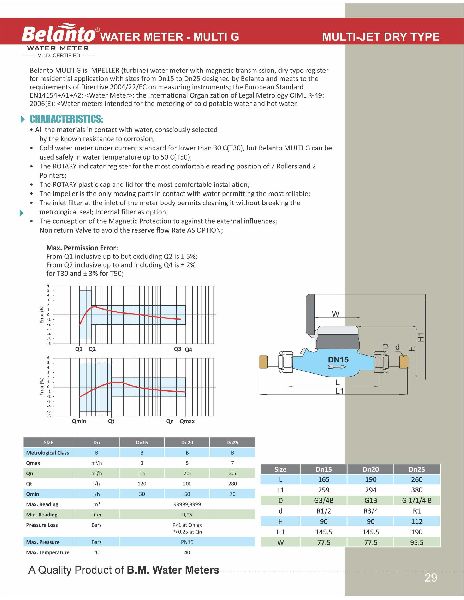
Belanto MULTI G is IMPELLER (turbine) water meter with magnetic transmission, dry type register for residential application with sizes from Dn15 to Dn25 designed by Belanto and meets to the requirements of Directive 2004/22/EC on measuring instruments; the European Standard EN141544-A1+A2, Water Meter, the International Organization of Legal Metrology OIML R-49: 2006(E):
Graph 01
Graph 02
Dimensions
| Size | mm | Dn 15 | Dn 20 | Dn 20 |
| R | Q3/Q1 | 80 | 80 | 80 |
| Q4 | m3/h | 3, 125 | 5 | 3, 125 |
| Q3 | m3/h | 2 , 5 | 4 | 2 , 5 |
| Q2 | L/H | 50 | 80 | 50 |
| Q1 | L/H | 31,25 | 50 | 31 , 25 |
| Specification As option | ||||
| R | Q3/Q1 | 50 | 50 | 50 |
| Q4 | m3/h | 2 | 3, 125 | 2 |
| Q3 | m3/h | 1, 6 | 2, 5 | 1, 6 |
| Q2 | L/H | 51.2 | 80 | 51.2 |
| Q1 | L/H | 32 | 50 | 32 |
| Max. Reading | m3 | 99999, 9999 | ||
| Min. Reading | Liter | 0.05 | ||
| Pressure Loss | P | P<63 at Q3 | ||
| Max. Pressure | MAP | MAP16 | ||
| Max. Temperature | oC | T30 or T50 | ||

Woltman (Turbine) Belanto WP-SDC is TURBINE Woltman water meter with magnetic transmission, super dry type register for industrial and irrigation application has the sizes from Dn40 to DnS00 designed by Belanto and meets to the requirements of Directive 2004/22/EC on measuring instruments and of European Standard EN14154.
Characteristics
n
Graph
Meter
Meter Dimensions
| DN | 40 | 50 | 65 | 80 | 100 | 125 | 150 | 200 | 250 | 300 | 350 | 400 | 500 |
|---|---|---|---|---|---|---|---|---|---|---|---|---|---|
| L | 260 | 200 | 200 | 225 | 250 | 250 | 300 | 350 | 450 | 500 | 500 | 600 | 800 |
| H | 225 | 252 | 262 | 272 | 282 | 297 | 341 | 371 | 480 | 516 | 560 | 647 | 785 |
| H1 | 303 | 339 | 349 | 359 | 369 | 384 | 428 | 458 | 576 | 603 | 603 | 723 | 838 |
| G | 360 | 400 | 400 | 400 | 400 | 400 | 500 | 500 | 710 | 730 | 730 | 830 | 930 |
| D | 150 | 165 | 185 | 200 | 220 | 250 | 285 | 340 | 405 | 460 | 520 | 580 | 715 |
| D1 | 110 | 125 | 145 | 160 | 180 | 210 | 240 | 295 | 355 | 410 | 470 | 525 | 650 |
| nxM | 4xM16 | 4xM16 | 4xM16 | 8xM16 | 8xM16 | 8xM20 | 12xM20 | 12xM20 | 12xM24 | 12xM24 | 16xM24 | 16xM27 | 20xM30 |
Dimensions
| Size | m3/Pulse | |
|---|---|---|
| Dn40 to Dn125 | 0.1 | 1 |
| Dn150 to Dn 200 | 1 | 10 |
| Dn 250 to Dn 500 | 10 | 100 |

Accuracy
n
Working Conditions
Graph 01
Graph 02
Graph 03
Technical Data
| Nominal Size Dn(mm) | Class of measurement | Overload Flow-rate qp(m3h) | Permannent Flow rate Qmin(m3h) | Transitional Flow rate QT(M3 H) | Minimum Flow rate qmin (m3h) | Minimum Reading min (m3) | Maximum Reading Max(m3) |
|---|---|---|---|---|---|---|---|
| 40 | B | 20 | 10 | 2 | 0.3 | 0.01 | 999999 |
| 50 | B | 30 | 15 | 3 | 0.45 | 0.01 | 999999 |
| 65 | B | 50 | 25 | 5 | 0.75 | 0.01 | 999999 |
| 80 | B | 80 | 40 | 8 | 1.2 | 0.01 | 999999 |
| 100 | B | 120 | 60 | 12 | 1.8 | 0.01 | 9999999 |
| 125 | B | 200 | 100 | 20 | 3 | 0.1 | 9999999 |
| 150 | B | 300 | 150 | 30 | 4.5 | 0.1 | 9999999 |
| 200 | B | 500 | 250 | 50 | 7.5 | 0.1 | 9999999 |
Overall Dimensions And Weight
| Size (mm) | Length (mm) L | Width (mm) W | Height (mm) H | Output diameter of flange D(mm) | The center diameters of connecting bolt D1(mm) | Connecting Bolt (Pcs.) | Weight (kg) |
|---|---|---|---|---|---|---|---|
| 40 | 245 | 165 | 253.5 | 165 | 125 | 4X16 | 12 |
| 50 | 200 | 165 | 247 | 165 | 125 | 4xM16 | 12 |
| 65 | 200 | 185 | 260 | 185 | 145 | 8xM16 | 13 |
| 80 | 225 | 200 | 264.5 | 200 | 160 | 8xM16 | 15 |
| 100 | 250 | 220 | 271.5 | 220 | 180 | 8xM20 | 19 |
| 125 | 250 | 250 | 295 | 250 | 210 | 8xM20 | 23 |
| 150 | 300 | 285 | 301.5 | 285 | 240 | 8xM20 | 30 |
| 200 | 350 | 340 | 358.5 | 340 | 295 | 12xM20 | 42 |

Salient Features :
nAccuracy :
nPerformance Data
| Nominal Size DN (MM) | Minimum Reading Quantity In liters | Hydro Static Test | Maximum Flow Rate Qmax-Lts/hr.) | Terminal flow rate qn-Lts,/ hr | Transitional Flow rate Qn-lts/ hr | Minimum starting Flow Qmin-lts/ hr |
|---|---|---|---|---|---|---|
| 15 | 0.1 | 2.0 Mpa | 3000 | 1500 | 120 | 30 |
Meter Dimensions
| Type | Size (mm) | Length (mm) L | Width (mm) W | Length inculding Nipple ± 5 % | Height (mm)H | Conneting Thread D |
|---|---|---|---|---|---|---|
| Multi jet | 15 MM | 165 | 81 | 250 | 100 | ¾ inch |
Head Loss Curve
Error Curve
Graph

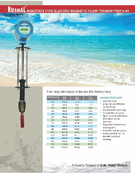
K-04 are Insertion type electromagnetic flow transmitter specially used for various industrial applications. These flow transmitters accurately measures to flow rate of conductive liquids & slurries in closed pipes. Due to simple & rigid design the flow transmitter is an obstruction less & maintenance free instrument in place of conventional mechanical flow measuring device. The use of 'Pulsed DC' technology offers highest ability & better measuring accuracy in the form of electrical signal 4-20 mA DC linearly proportional to volumetric flow. The instrument is based on Faraday's law of electro-magnetic induction. A magnetic field is generated by the instrument in the flow tube. The fluid flowing through this magnetic field generates a voltage that is proportional to the velocity. Corresponding electrical output is provided with respect to measuring voltage.
nnFeatures :
nGraph
Technical Details
| Line size(mm) | Flow (m3/ hr) | Flow (MLD) | Flow (ft3/sec) |
|---|---|---|---|
| 200 | 113.1 | 2.714 | 1.109 |
| 250 | 176.71 | 4.241 | 1.734 |
| 300 | 254.47 | 6.107 | 2.496 |
| 350 | 346.36 | 8.313 | 3.398 |
| 400 | 452.39 | 10.857 | 4.438 |
| 500 | 706.86 | 16.965 | 6.934 |
| 600 | 1017.88 | 14.429 | 9.985 |
| 700 | 1385.44 | 33.25 | 13.251 |
| 800 | 1809.56 | 43.429 | 17.751 |
| 900 | 2290.22 | 54.965 | 22.466 |
| 1000 | 2827.43 | 67.858 | 27.736 |
| 1200 | 4071.5 | 97.716 | 39.94 |
| 1400 | 5541.76 | 133.002 | 54.363 |
| 1600 | 7238.22 | 173.717 | 71.004 |
| 1800 | 9160.88 | 219.861 | 89.865 |
| 2000 | 11309.72 | 271.433 | 110.944 |

Salient Features
nAccuracy :
nHead Loss Curve
Error Curve
Graph
Meter Dimensions
| Type | Size (mm) | Length (mm) L | Width (mm) W | Length inculding Nipple ± 5 % | Height (mm)H | Conneting Thread D |
|---|---|---|---|---|---|---|
| Single Jet | 15 MM | 110 | 77 | 250 | 82 | ¾ |
| Single Jet | 20 MM | 130 | 78 | 200 | 85 | 1 |
Performance Data
| Nominal size DN (MM) | Minimum reading quantity in liters | Hydro static Test | Maximum Flow Rate Qmax-Lts/hr.) | Nominal flow rate qn-lts/hr | Transitional flow rate qn-lts/hr | Minimum starting flow rate q Min-lts/hr |
|---|---|---|---|---|---|---|
| 15 | 0.2 | 2.0 Mpa | 3000 | 1500 | 120 | 30 |
| 20 | 0.2 | 2.0 Mpa | 5000 | 2500 | 200 | 50 |

Features :
nAccuracy :
nHead Loss Curve
Dimension Curve
Error Curve
Technical Details
| Type | Size (mm) | Length (mm) L | Length inculding Nut Nipple (mm) | Width (mm) W | Height (mm)H | Conneting Thread D |
|---|---|---|---|---|---|---|
| Multi jet Class B King | 15 | 165 | 250 | 97 | 109 | G ¾ B |
| 20 | 190 | 290 | 98 | 110 | G 1 B | |
| 25 | 260 | 380 | 104 | 117 | G ¼ B | |
| 40 | 300 | 430 | 125 | 148 | G 2 B | |
| 50 | 330 | 470 | 125 | 148 | G 2 ½ B |
Performance Data
| Nominal Size DN (MM) | Minimum Reading Quantity In liters | Hydro Static Test | Maximum Flow Rate Qmax-Lts/hr.) | Terminal flow rate qn-Lts,/ hr | Transitional Flow rate Qn-lts/ hr | Minimum starting Flow Qmin-lts/ hr |
|---|---|---|---|---|---|---|
| 15 | 0.1 | 2.0 Mpa | 3000 | 1500 | 120 | 30 |
| 20 | 0.1 | 2.0 Mpa | 5000 | 2500 | 200 | 50 |
| 25 | 0.1 | 2.0 Mpa | 7000 | 3500 | 280 | 70 |
| 40 | 0.1 | 2.0 Mpa | 20000 | 10000 | 800 | 200 |
| 50 | 0.1 | 2.0 Mpa | 30000 | 15000 | 1200 | 300 |

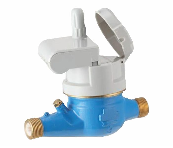
Petroleum Metering Equipment & Accessories Mechanical volumetric flow-meter for private use, with Nutating-disc type chamber for delivers to 120 LPM. It can be installed for gravitational feeding, as well as for hand operated or electric transfer pumps with by-pass arrangement.
nnFluid Compatibility The DM-01 series meters are compatible with the following fluids : Diesel, Gasoline, Kerosene, Methanol
n
Installation
Graph
Meter
Technical Details
| Meter Mechanism | Nutating disk |
|---|---|
| Flow Rate (range) | 20-21I /MIN(5.28-31.7 Gal/min) |
| Operating pressure (max) | 3.5 bar (49psi) |
| Brust pressure (max) | 30 bar (420 psi) |
| Storage time (range) | -20±80o |
| storage Humidity (max) | 95.00% |
| operating temperature (range) | -10±60o |
| Accuracy after calibration | +/-1% |
| repeatability (typical) | +/- 0.3% |
| Readout solution | 0.1L/Gal |
| connection (inlet/oulet) | 1 inch BSP/NPT |
| weight (approximate) Package dimension | 1.8 kg 18x16x14 cm |


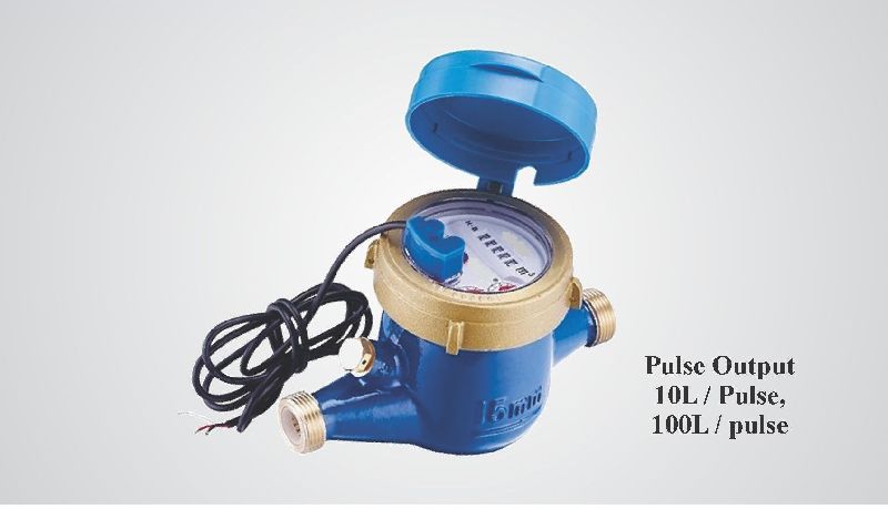
BELANTO make Domestic Water Meter As per IS 779:1994 / ISO 4064/1/ MID

BELANTO Make Domestic Water meter Brass Body as per IS 779:1994/ ISO 4064/1
"KUSHAL" MAKE ELECTROMAGNETIC FLOW METER