Our Products
Our product range contains a wide range of Hot Press, Hand Press Brakes, Mechanical Clutch Bending Press Brakes, Fly Presses and Power Operated Hydraulic Press

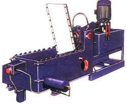
Hot Press is used to press and paste the mica to the board. In this machine the mica and the particle board are bonded together with the help of adhesive and heat of electrical heaters. The adhesive is applied on the board the mica and are placed in the machine. The heaters at the set temperature are heated and maintain that temperature automatically and the bottom plates of the press with the help of a switch start moving toward the upward direction. At the set pressure the plate will stop and start moving downward at the interval set by the user. Remove the board, mica is pasted on the board is ready for use.

Hand operated all steel welded construction press brake ideally suitable for bending sides of rolling shutters, cupboard, cabinets, trays, boxes and many other objects provided with bending die with various size of grooves having following specifications. Bending Width :4', 6', 7', 8'
Capacity in M.S. :1/16", 1/8"

Press Brakes are designed and developed through years of experience in sheet metal working machines. Press Brakes are widely accepted in industries for continuous production runs and in areas requiring accuracy and repeatability coupled with high production. Frame : Frame is of robust fabricated steel construction of rigid and interlocked design. It is stain-free and supports the ram and bed against desired deflection under permissible loading condition. Ram and bed : Made from steel plates of suitable thickness, machined for straightness and parallelism of working surfaces. Ram is guided and supported throughout the stroke by accurately machined guideways.
Drive system : Power is transmitted to the ram through two individual gear drives for uniform load distribution throughout the length. This also reduces the torsional stresses on the eccentric shaft. Electric motor used is of sufficient H.P. which reduces slowdown of fly wheel and increases energy available per stroke. The gear and pinion are made out of carbon/alloy steel. Ram Adjustment : Motorised ram adjustment through a simple drive mechanism, faciliates quick bending angle adjustment. Angular ram adjustment made simple by incorporating a spring loaded dog clutch. Clutch and brake : All series of press brakes are provided with high-torque tow-inertia friction clutch synchronised with heavy duty mechanical brake ensuring immediate braking of ram on releasing the pedal Clutch operating levers are designed in such a way that minimum enraging force is required at the pedal. Special Features : Connection link mounted on crank shaft for uniform load, separate Drive system for each connection link, Sufficient H.P Normal torque motors provided. Boltless pedal mounted on hexagonal bar. General purpose V-Block and punch supplied as standard accessories.
Pneumatic Clutch & Brake : Electrically controlled & Air operated Clutch & Brake combine unit permits high frequency of ooperation and more Flywheel energy for work. Wear on Clutch & Brake is automatically compensated & no adjustment is necessary. Surge Tank, Filter, Regulator, Air Lubrication Unit, Pressure Switch etc. are incorporated. Pneumatic Counter Balancer are provided to Counter the Weight of Slide & Tooling which help in taking up the bearing clearances and ease Slide adjustment.
Standard Accessories : Standard V-block and Punch, Back Gauge, Electrical consist of Electric Motor, Wiring, Control Panel, V-belt, Push Button Starter, Motor pulley, Motor Mounting Bracket, Pedal, Flywheel & Gear Guards, Stroke Counter, Lubrication Pump & Instruction Manual. Optional Accessories : Automatic Pump Lubrication System, Goose Neck Punch, & other toolings (Drawing required).
| Model | Tonnag | Clear Distance Between Housings G | Bending cap. in M.S Leng. x Thick. | Main motor HP/KW | Ram Adj. Ele motor HP/KW | Stroke per Min. | Stroke of Ram M.M. | Ram Adj. MM Stroke Down | Shut Height Ram | Depth of Throat MM | Overall Dimensions in mm | ||
| Leng. A | Bread. B | Heig. C |
|||||||||||
| AMI-0 | 20 | 990 | 1525x1.6 | 3/2.2 | Manual | 30 | 50 | 40 | 200 | 240 | 1800 | 1100 | 2300 |
| AMI -1 | 25 | 1220 | 2030x1.6 | 5/3.7 | 1/.75 | 30 | 50 | 40 | 200 | 240 | 2300 | 1150 | 2300 |
| AMI-2 | 65 | 1220 | 2030 x 4 | 7.5/5.6 | 1.5/1.0 | 30 | 75 | 75 | 220 | 300 | 2300 | 1150 | 2300 |
| AMI-3 | 80 | 1700 | 2540 x 4 | 10/7.7 | 1.5/1.0 | 30 | 75 | 75 | 220 | 300 | 2900 | 1500 | 2850 |
| AMI-4 | 100 | 1700 | 3125 x 4 | 15/11.2 | 2/1.5 | 25 | 75 | 75 | 275 | 300 | 3400 | 1800 | 3400 |
| AMI-5 | 100 | 1700 | 2540 x 5 | 15/11.2 | 2/1.5 | 25 | 75 | 75 | 275 | 300 | 2900 | 1800 | 3400 |
| AMI-6 | 125 | 1700 | 3125 x 5 | 20/15 | 2/1.5 | 25 | 75 | 75 | 275 | 300 | 3400 | 1800 | 3400 |
| AMI-7 | 120 | 1700 | 2540 x 6 | 20/15 | 2/1.5 | 25 | 75 | 75 | 275 | 300 | 2900 | 1800 | 3400 |
| AMI-8 | 150 | 1900 | 3125 x 6 | 25/18.7 | 2/1.5 | 25 | 75 | 75 | 275 | 300 | 3400 | 1800 | 3400 |
| Model | Tonnag | Clear Distance Between Housings G | Bending cap. in M.S Leng. x Thick. | Main motor HP/KW | Ram Adj. Ele motor HP/KW | Stroke per Min. | Stroke of Ram M.M. | Ram Adj. MM Stroke Down | Shut Height Ram | Depth of Throat MM | Overall Dimensions in mm | ||
| Length A | Breadth B | Height C |
|||||||||||
| AMI-9 | 160 | 1700 | 2540 x 8 | 25/18.7 | 2/1.5 | 25 | 75 | 75 | 275 | 300 | 3000 | 1900 | 3400 |
| AMI - 10 | 200 | 1000 | 3125 x 8 | 30/22.5 | 2/1.5 | 20 | 75 | 75 | 275 | 300 | 3400 | 2000 | 3600 |
| AMI-11 | 200 | 1700 | 2540 x 10 | 30/22.5 | 2/1.5 | 20 | 100 | 75 | 275 | 300 | 3100 | 2000 | 3600 |
| AMI-12 | 250 | 2500 | 3500 x 10 | 40/30 | 3/2.2 | 20 | 100 | 75 | 275 | 300 | 4100 | 2150 | 4000 |

Hand Fly Presses with two adjustable Vee guides provided with oil grooves for constant lubrication complete with 2 catch dogs with bolts and nuts. Fly wheel or handle with ball weights as desired (fly presses no. 0.1 & 2 are supplied with fly handle with one ball weight only or wheel as desired).
| No. | Centre to back | Base to guide | Dia of Screw |
| 0 | 3.1/2" | 4.3/4" | 1.1/8" |
| 1 | 3.1/2" | 5.1/2" | 1.3/4" |
| 2 | 4" | 6" | 1.7/8" |
| 3 | 4.1/2" | 6.1/2" | 2" |
| 4 | 5" | 6.3/4" | 2.1/8" |
| 5 | 5.3/4" | 7.1/4" | 2.5/8" |
| 6 | 6.1/2" | 7.1/2" | 2.1/4" |
| 7 | 6.1/2" | 8" | 2.5/8" |
| 8 | 6.1/2" | 8.1/2" | 2.3/4" |
| 9 | 7" | 8.3/4" | 2.3/4" |
| 10 | 7.5/8" | 9" | 3" |

Simple Operction : Press is provided with motorised pump unit and a hand-operated, control valve. Pump is driven by flange coupled motor and has a pressure adjusting valve for adjustment of high pressure. High quality hydraulic unit : Cyclinder is made of special steel that secures absolute pressure tightness. The seals are made of special material and guarantee long life. PISTON ROD & PISTON HEAD are carefully ground and hard chrome plated to obtain closest, accuracy in guiding. Precision Pressing : Actual pressure may be read in tons from the precision pressure gauge that has red zone from maximum pressure and upwards. Press beds are planned off and as standard equipment. 2 PLANED OFF STRAIGHTEN V BLOCKS are supplied.
| Tons | Between Column | Between Ram to Bed | Travel of | Motor H.P. | ||||
| length | X | Breadth | Min | Max. | Ram | |||
| mm | mm | mm | mm | mm | mm | |||
| 5 | 500 | X | 125 | 75 | X | 600 | 100 | 3 |
| 10 | 600 | X | 150 | 75 | X | 600 | 125 | 3 |
| 15 | 650 | X | 150 | 75 | X | 600 | 150 | 3 |
| 25 | 850 | X | 300 | 180 | X | 910 | 180 | 5 |
| 40 | 950 | X | 350 | 180 | X | 910 | 190 | 5 |
| 50 | 1000 | X | 400 | 180 | X | 9S0 | 200 | 5 |
| 60 | 1050 | X | 450 | 180 | X | 975 | 200 | 7.5 |
| 75 | 1180 | X | 500 | 180 | X | 975 | 210 | 7.5 |
| 100 | 1200 | X | 600 | 180 | X | 97S | 225 | 10 |
| 180 | 1300 | X | 625 | 180 | X | 975 | 240 | 15 |
| 200 | 1325 | X | 660 | 180 | X | 976 | 240 | 20 |
| 250 | 1350 | X | 650 | 180 | X | 975 | 250 | 25 |
| 300 | 1450 | X | 700 | 180 | X | 1000 | 260 | 30 |
| 500 | 1500 | X | 1000 | 200 | X | 1100 | 300 | 50 |

The sturdy construction of all presses gurantees stability ond durability. The Press is provided within a 2 stage hand pump. The low pressure pump is used for rapid advance of piston at low pressure. The high pressure Pump is provided with a special material lining and is used for slow advance at high pressure. The winch provided for raising and lowering the table is smooth running. During operation the table is fastened by means of pins. The press has been all welded Standard accessories and planned off V Block for straightening.

Hand operated bench mounting standard single station punch press, a multi-purpose precision machine which perforates holes of various sizes, and shapes upto 4" dia in 16 gauge steel-rapidly and efficiently. Used also for an unlimited variety of blanking, drawing, embissing and forming operations. Adjustable side and back gauges incorporated in the machine allow precision gauging for exacting duplicating operations. Perfect alignment of the punch head is assured at all times by a dove-tail shaped ram which is hardened and precision ground. The roller cam provides tremendous pressure at the point of impact. Standard Equipment : Standard equipments includes punch holder, for punches with 1/2" dia, shank die holder, short and long handle, for operator convenience. Side and back gauges. Extra Equipments : Stand, Different types of dies & punches.
| Model No. | AMI-6 | AMI -12 |
| Depth of throat | 6" | 12" |
| Rated Capacity | 4 tons | 4 tons |
| Height of throat | 3" | 3" |
| Stroke | 5/8" | 5/8" |
| Hole in Ram (Diameter) | 1" | 1" |
| Bed Dimensions | 6" x 7.1/2" | 6" x 7.1/2" |
| Slug Waste hole | 4.1/4" x 5.3/4" | 4.1/4" x 5.3/4" |
| Floor Space (on stand) | 15" x 17" | 15" x 26" |
| Weight approx. | 85 Kgs. | 170 Kgs. |

Standard Accessories :
|
|
| Maximum Pressure | 25 Tons |
50 Tons |
75 Tons |
100 Tons | 150 Tons | 200 Tons | 250 Tons |
300 Tons |
| Stroke | 56 MM | 75 MM | 87 MM | 100 MM | 125 MM | 150 MM | 150 MM | 150 MM |
| Bed to ram bottom | 275 | 300 | 325 | 425 | 475 | 500 | 525 | 550 |
| Distance between upright | 425 | 475 | 550 | 625 | 675 | 725 | 800 | 875 |
| Size of Press Table | 425 x 400 | 475 x 500 | 550 x 575 | 625 x 675 | 675 x 725 | 725 x 800 | 800 x 875 | 875 x 875 |
| Diameter of hole in ram | 28 | 31 | 37 | 43 | 50 | 68 | 75 | 75 |
| No. of strokes per minute | 60 | 55 | 40 | 30-35 | 30 | 30 | 27 | 22 |
| Speed of Fly Wheel | 402 | 320 | 250 | 175 | 175 | 160 | 160 | |
| Power required (1440 RPM) | 2 HP | 3 HP | 5 HP | 7.1/2 HP | 10 HP | 15 HP | 20 HP | 25 HP |
| Size of opening Table | 150 | 175 | 187 | 200 | 250 | 275 | 300 | 300 |
| Section of V Belts | B | B | C | C | C | C | C | |
| Gear Dia | 600 | 650 | 750 | 850 | 1000 | 1200 | 1250 | 1350 |
| Fly Wheal Dia | 600 | 775 | 900 | 950 | 1050 | 1250 | 1250 | 1350 |
| Gross Weight | 1400 Kgs. |
2100 Kgs. | 3080 Kgs. | 4600 Kgs. |
5550 Kgs. |
8500 Kgs. |
11000 Kgs. | 16000 Kgs. |