Our Product / Services
Our Complete range of products are Ultrasonic Testing, Vacuum Box Leak Testing, DAKS TOOLS NDT Standard Flawed Specimens Kit - (UT,MT,PT,RT & VT), Remote Field Eletromangnetic Testing and Tubular Nodes12mm, 30deg UT Flawed Specimens (As Per BINDT PCN Classification Specimens).

Manual Ultrasonic Testing
MANUAL ULTRASONIC TESTING
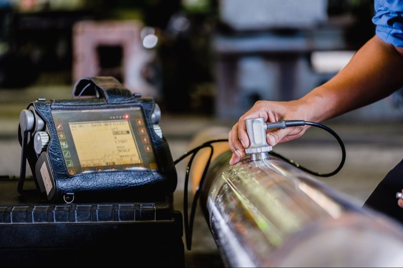
Manual ultrasonic testing is a form of NDT used to detect internal discontinuities, material thickness, and part integrity.
Ultrasonic testing is used to carry out the inspection in casting, forging, welded components in all industrial sectors.
The method can be performed on all types of materials:
Defects that are small and deep in the surface.
To detect object thickness.
Assessment of part integrity.
Its major advantage is quick and portable inspection.
Alpha Sonix uses advanced ultrasonic equipment and we can inspect customers components and structures according to industry codes and standards or customer specifications, ensuring that components or structures meet the highest quality standards for safety and reliability. We offer both off-site and on-site ultrasonic testing.
The technique uses a pulse unit to power an ultrasonic transducer. The transducer is placed into contact with the tested object with a thin layer of Couplant and sound waves are generated into the object. The reflected waves are assessed and the signals from the echo are shown on the display unit.
Skilled interpretation of the signals indicates if there are any defects or discontinuities.Our experienced ultrasonic inspectors are certified according to industry standards in ASNT level 2 and 3. They offer guidance in the selection of suitable testing methods and regiment.
By choosing Alpha Sonix for your ultrasonic testing, we can meet your production and maintenance schedules. And our highly experienced inspectors use advanced equipment to give you the Total Quality Assurance that your products or components are compliant with industry standards.
Other advanced ultrasonic testing methods provide by Alpha Sonix:
Alpha Sonix not only provide manual ultrasonic testing, but we also offer advanced ultrasonic testing that includes:
Time of flight diffraction (TOFD)
Ultrasonic Thickness Measurement
Phased array
Immersion ultrasonic testing

We are ranked amongst the renowned organizations that are engaged to provide the best qualityVacuum Box Leak Testing Service.The offered service is executed by our highly qualified professionals using premium grade machines and latest technology. Our skilled professionals properly examine all the parameters associated to this service and carry out it in the best possible manner. Further, the provided service is performed as per the clients specific needs with respect to their budgetary constraints.
")
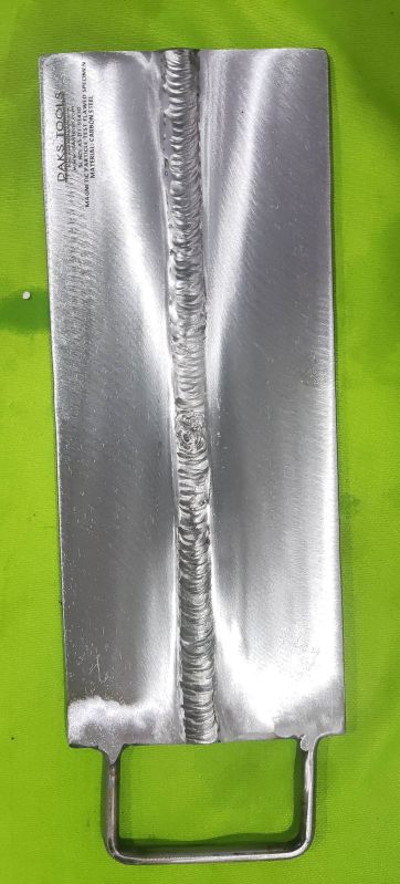
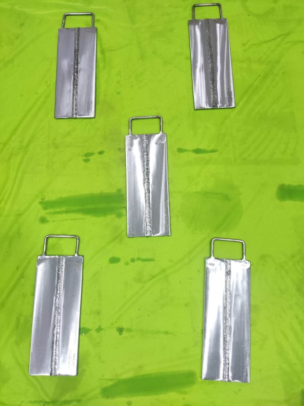
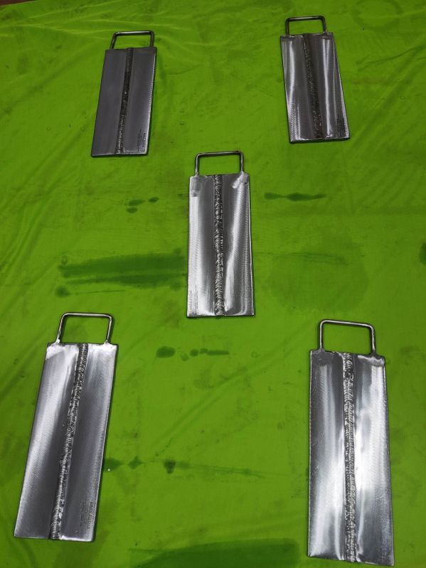
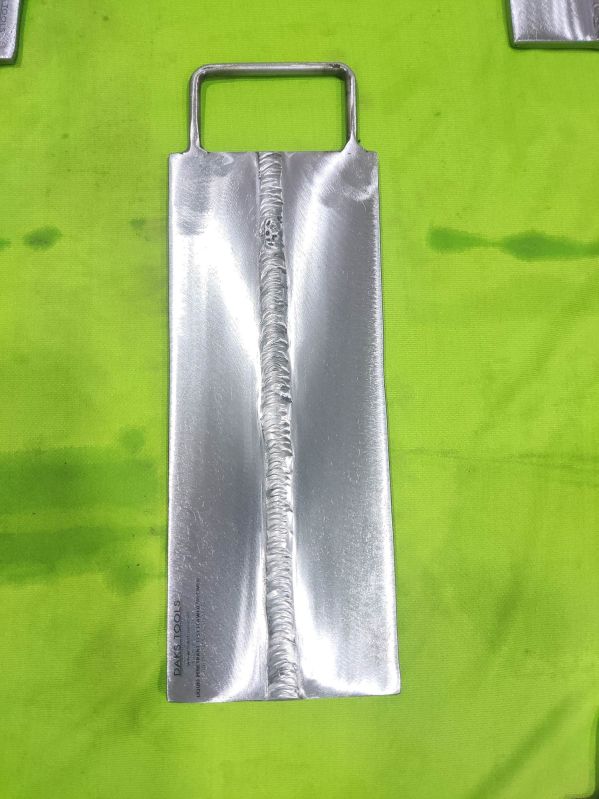
Total Number Of Specimen:[6] - 3 Plates, 2 Pipe and 1 Tee.
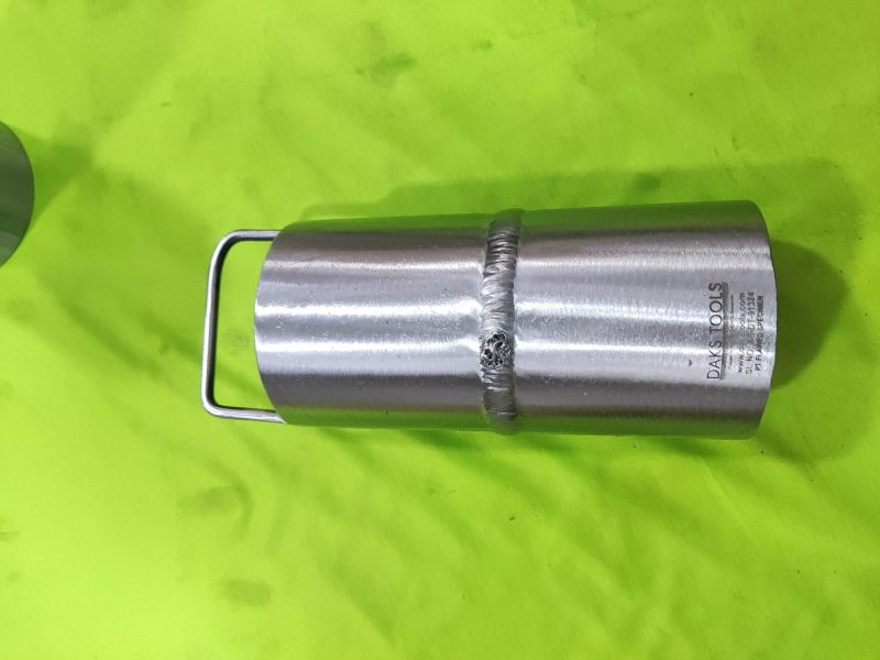
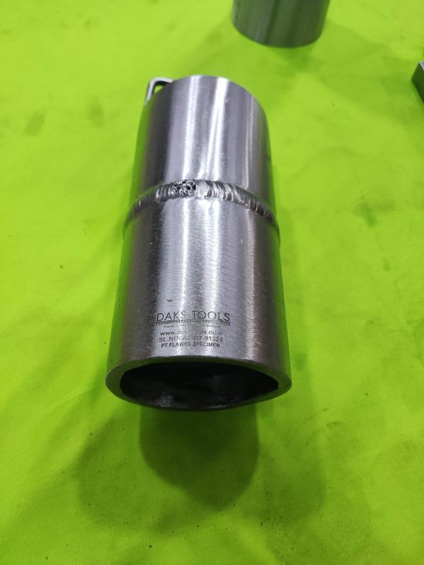
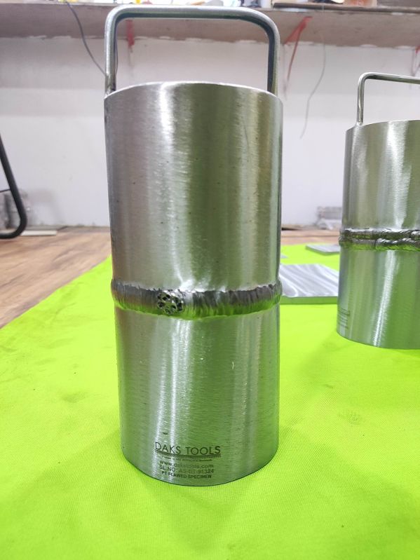
Kit Contents :6 specimens MT (1) Tee @6mmT x 100mm x 200mm x 100mm, VT (1) Plate @ 6mmT x 100 x 200, PT (1) Plate @6mm x 100mm x 200mm, UT (1) Plate @ 15mmT x 100mm x 200mm, RT (1) Pipe 100mm Sch80 (8mm wall) x 200mm, PT (1) Pipe 100mm Sch80 (8mm wall) x 200mm.
Specimens:Plate, Pipe, Tee Joint
Flaws:2 to 3 each specimen
Documentation:NDT Verification Reports And CAD Drawings and Test Sheets.
Material :

In the realm of non-destructive testing, remote field testing, or "RFET, " is one of numerous electromagnetic testing procedures routinely used. Magnetic flux leakage, conventional eddy current, and alternating current field measurement testing are some of the other electromagnetic inspection methods. Remote field testing is frequently referred to as "Remote Field Electromagnetic Testing" since it is related with eddy current testing. However, there are a few key distinctions between eddy current and remote field testing that will be discussed in this section.
Due to the substantial skin effect in ferromagnetic materials, standard eddy current techniques have difficulties inspecting the complete thickness of the tube wall. RFET is primarily used to inspect ferromagnetic tubing.
For example, utilising traditional eddy current bobbin probes to inspect a 10 mm thick steel pipe (such as those found in heat exchangers) would necessitate frequencies about 30 Hz to obtain appropriate I.D. to O.D. penetration into the tube wall. Because of the low frequency, the sensitivity of fault detection is quite low. The use of partial saturation eddy current probes, magnetically biassed probes, and pulsed saturation probes can theoretically improve the degree of penetration.These specialised eddy current probes, however, are still limited in their examination capabilities due to the enormous amount of metal present as well as potential permeability fluctuations inside the product.
The employment of the remote field-testing approach can substantially reduce the challenges encountered in the testing of ferromagnetic tubes. The advantage of the RFET approach is that it allows for approximately similar detection sensitivities on both the inner and outer surfaces of a ferromagnetic tube. Variations in wall thickness are very sensitive to the approach, although fill-factor changes between the coil and tube are less sensitive. When checking conducting tubular products, RFET can be employed, but it is typically thought to be less sensitive than traditional eddy current procedures.
This is a quick and accurate screening tool for determining the condition of ferrous tubing (carbon steel, ferritic stainless steel and Duplex). It can inspect up to 12 mm (1/2 in.) of carbon steel tubing at very low frequencies (100 Hz to 1 kHz) and very high signal gains (> 80 dB). For most examinations, two channels are used: absolute for wall thinning and differential for localised abnormalities. RFT is excellent at measuring wall thinning but not so good for pitting (as compared to ECT). Cleaning the internal bore of tubes with any type of water jet lancing equipment is always recommended to improve inspection findings.
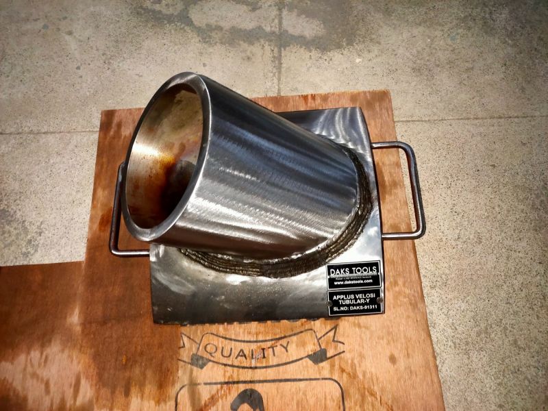
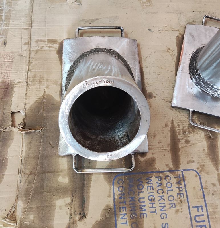
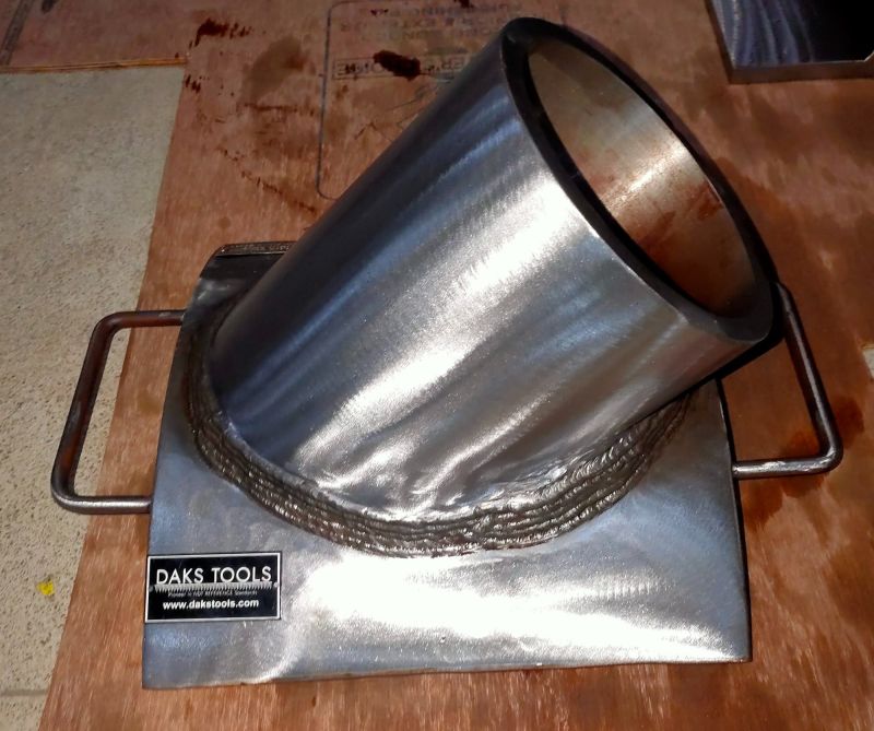
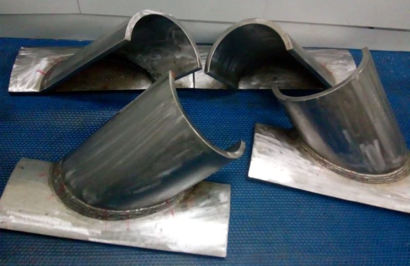
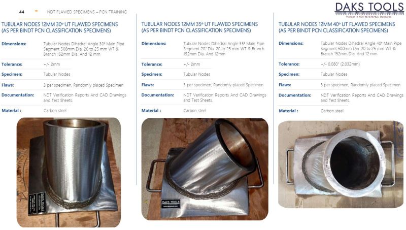
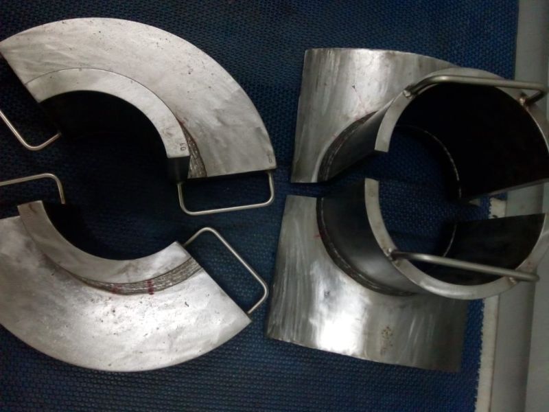
Tubular Nodes 12mm 30deg UT Flawed Specimens ( As per BINDT PCN Classification Specimens ) Dimensions : Tubular Nodes Dihedral Angle 30deg Main Pipe Segment 508mm Dia. 20 to 25 mm WT & Branch 152mm Dia. And 12 mm WT (Carbon Steel) Material : Carbon Steel Flaws : 3 per specimen, Randomly placed Specimen Tolerance: +/- 2mm Documentation: NDT Verification Reports And CAD Drawings and Test Sheets.
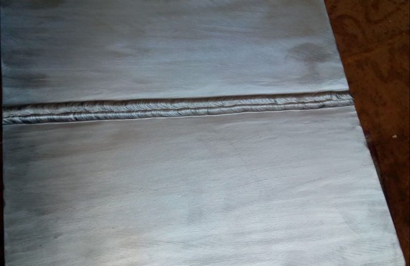
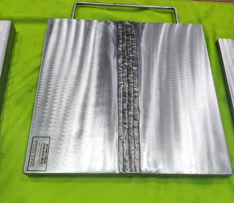
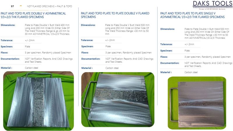
PHASED ARRAY AND TOFD PLATE DOUBLE V FLAWED SPECIMENS
Dimensions:Plate to Plate Double V Butt Weld 400mm Long And 200mm Wide On Either Side Of The Weld Thickness Range > 20mm to 30mm.
Tolerance:+/- 2mm
Specimen:Plate
Flaws:3 per specimen, Randomly placed Specimen
Documentation:NDT Verification Reports And CAD Drawings and Test Sheets.
Material:Carbon steel
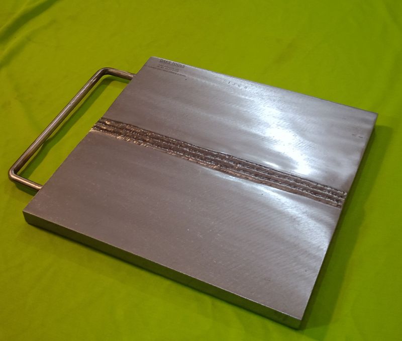
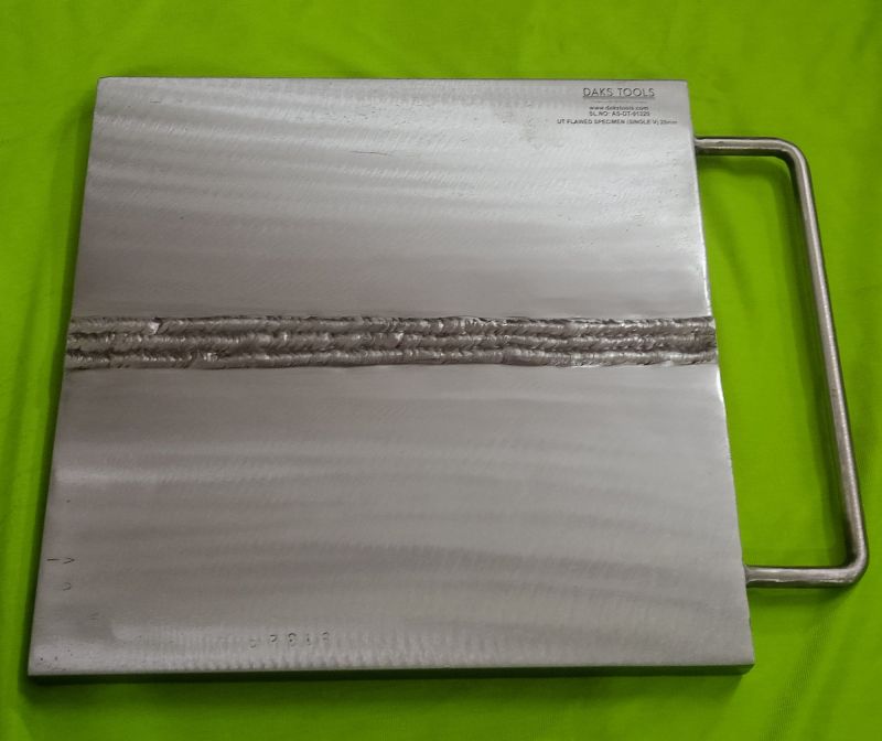
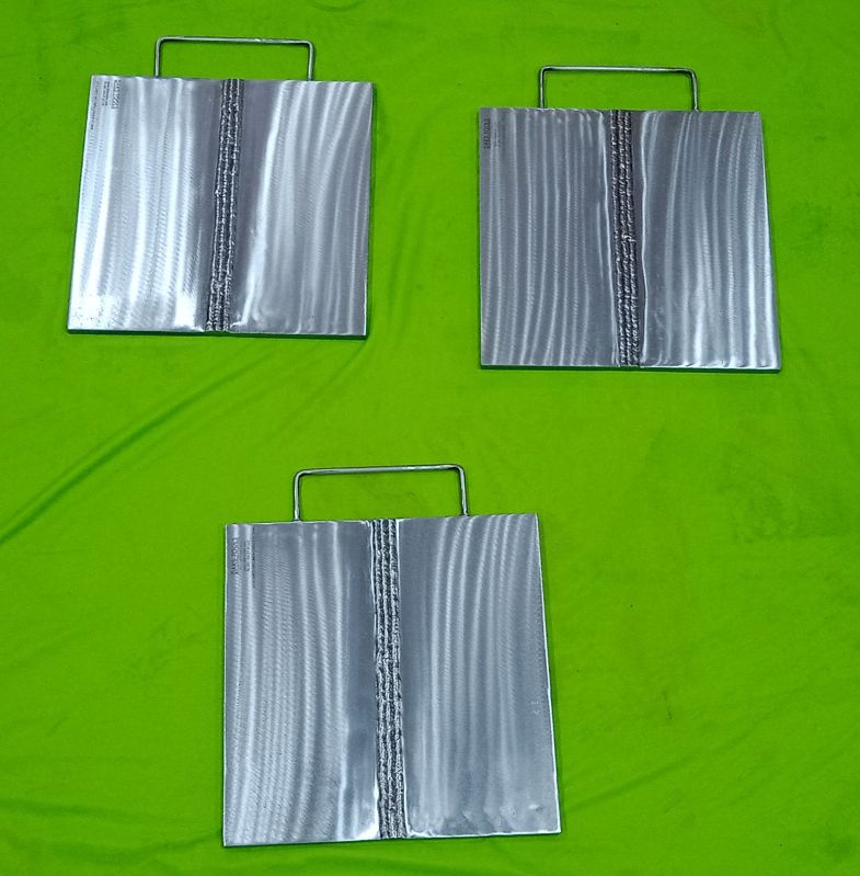
PAUT AND TOFD PLATE TO PLATE SINGLE V FLAWED SPECIMENS
Dimensions:Plate to Plate Single V Butt Weld 500mm Long and 250 mm Wide on Either Side of The Weld and Plate thickness Range > 30mm to 50mm.
Tolerance:+/- 2mmSpecimen:PlateFlaws:3 per specimen, Randomly placed SpecimenDocumentation:NDT Verification Reports And CAD Drawings and Test Sheets.Material:Carbon steel
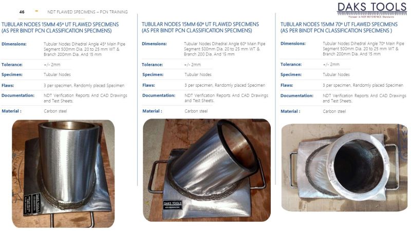
TUBULAR NODES 15MM 60Deg UT FLAWED SPECIMENS (AS PER BINDT PCN CLASSIFICATION SPECIMENS)
Dimensions:Tubular Nodes Dihedral Angle 60 Main PipeSegment 500mm Dia. 20 to 25 mm WT &Branch 200 Dia. And 15mm.
Tolerance:+/- 2mm
Specimen:Tubular Nodes
Flaws:3 per specimen, Randomly placed Specimen
Documentation:NDT Verification Reports And CAD Drawings and Test Sheets.
Material:Carbon steel.

Residual/Remaining Life Assessment (RLA) & Condition Assessments of Boilers
Considering the operational conditions to which the equipment is subjected, determining the remaining life of an asset necessitates a thorough understanding of the degradation mechanisms and their progression.
RLA assessments are performed by ALPHA SONIX in the most difficult markets. ALPHA SONIX uses advanced analytical and simulation techniques in addition to its multidisciplinary in-house team to give accurate results and superior value to the decision-making process.
Many businesses and power plants have the challenge of predicting the remaining operational life of plant equipment that has been in use for many years. The issue is particularly acute for businesses with plants that have been in operation for 15 to 25 years or longer.In the maintenance decision-making process, reliability data analysis is critical. The ability to accurately estimate the remaining life of equipment and system components can be a valuable asset when planning preventative maintenance. To achieve high operational availability and maintenance stability in order to extend the life of equipment.
BOILER AND ITS COMPONENTS CONDITION EVALUATION
RLA is a method/test for inspecting and testing boilers and heaters that have been in use for a long time. RLA is a maintenance tool that can be used to predict and avoid problems before they occur.
Using both non-destructive and destructive procedures, condition assessment is carried out to determine the current status of component property degradation. Condition evaluation is critical for keeping facilities running smoothly and meeting increasingly demanding environmental laws, planned outages, adequate maintenance, and data collecting in new and old plants alike. Rather of being a one-time event, it is a continuous process.
Approach to Determining How Much Time Is Left In My Life
1. Determining the true process of degradation High Cycle Fatigue Low Cycle Fatigue Thermal Fatigue Thermo Mechanical Fatigue Thermal Aging Wear Creep Embitterment Corrosion
2. Physical Property Visual Inspection
3. Nondestructive testing (NDT) that includes in-situ metallography, ultrasonic testing, magnetic particle inspection, DP testing, and ferrite measurement.
4. Stress analysis: To determine the material's strength and check for ruptures.
5. Non-Destructive Testing (NDT): To determine the component's integrity.
6. Laboratory testing: To provide useful information regarding the material's structural integrity.
7. Equipment fitness assessment: based on data provided.
8. Maintenance Suggestions: If necessary, equipment repair is recommended to extend its life.
9. Remaining Life Judgment Based on Analysis: Estimates for remaining life are made. In addition, periodic inspection processes are written out to keep track of the equipment's health while it's in use.

Magnetic Particle Inspection (MPI)
MAGNETIC PARTICLE INSPECTION
Magnetic Particle Inspection (MPI) is an NDT method that can use magnetism to detect surface and subsurface discontinuities in ferromagnetic materials.
MPI is generally used to determine parts fitness for use. It is a relatively easy and quick method that is widely used in various sectors such as automotive, oil and gas, aerospace, petroleum, power generation, etc.
This method detects surface or subsurface discontinuities such as cracks, porosity, laps, seams, inclusions in ferromagnetic materials. One of the major advantages of this method is, it is a relatively fast method and gives an immediate indication on the surface.
This method works by inducing the magnetic flux in the part to be tested. If any discontinuities or detect is present on the surface or near the surface the magnetic field distorts and leaks around the defect. By application of magnetic medium on the surface, the particles attract the area where flux leakage has occurred producing a visible indication of the defect. This indication can be evaluated by the operator any necessary measures are taken if any.
Our techniques for magnetic particle inspection include:
Yoke
Bench (for headshot direct induction)
Coil shot
Prods
Central conductor
ALPHA SONIX has skilled NDT personnel that have gained years of experience in performing MPI and areLevel 2 and 3 qualified withASNT. We provide the testing both on-site at our customers premises.
When selecting ALPHA SONIX for your magnetic particle inspection (MPI) needs, you have an assurance that your maintenance schedules will be met and you will benefit from the expertise that our inspectors provide. Our reports will provide you with the necessary data to take preventive measures and will help in the management of assets.

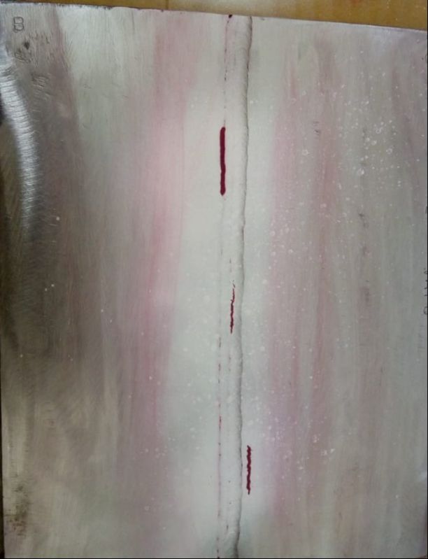
Being a leader in this industry, we are devoted towards providing a premium qualityDye Penetrant Testing Service.This service is performed as per the requirements of our precious clients. The provided service is highly appreciated by our clients owing to its hassle free execution and cost-effectiveness features. This service is carried out by our highly qualified professionals using excellent grade tools and modern technology. The offered service is executed within a scheduled time-frame. Furthermore, provided services can be availed by our valuable clients at most competitive prices.

With enriched industrial experience and knowledge, we are providing a qualitativeNDT Visual Testing Service.The provided service is executed as per the requirements of our precious clients. Our experts check all the steps and parameters associated to this service and carry out it in the best possible manner. Our professionals use high grade tools and latest technology to execute this service. Furthermore, the offered service can be availed by our precious clients at most reasonable price.
Our services include fresh & hardened concrete mortar and screed tests.
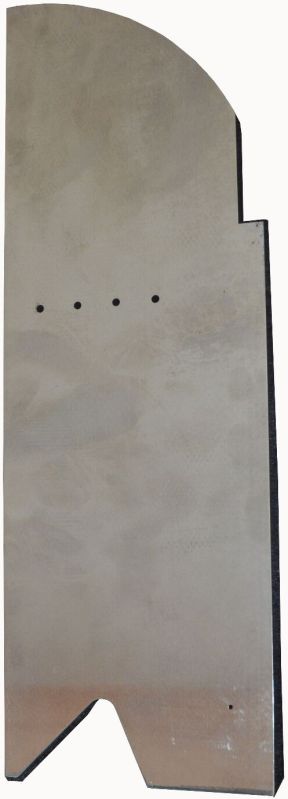
TUBULAR NODES 15MM 70 UT FLAWED SPECIMENS (AS PER BINDT PCN CLASSIFICATION SPECIMENS)
Dimensions:Tubular Nodes Dihedral Angle 70 Main Pipe Segment 500mm Dia. 20 to 25 mm WT & Branch 200mm Dia. And 15mm.
Tolerance:+/- 2mm
Specimen:Tubular Nodes
Flaws:3 per specimen, Randomly placed Specimen
Documentation:NDT Verification Reports And CAD Drawings and Test Sheets.
Material:Carbon steel.
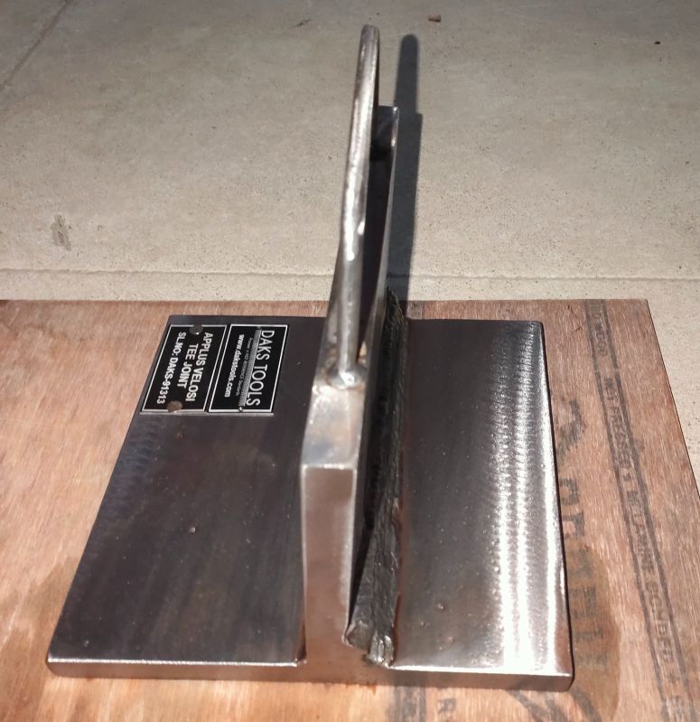
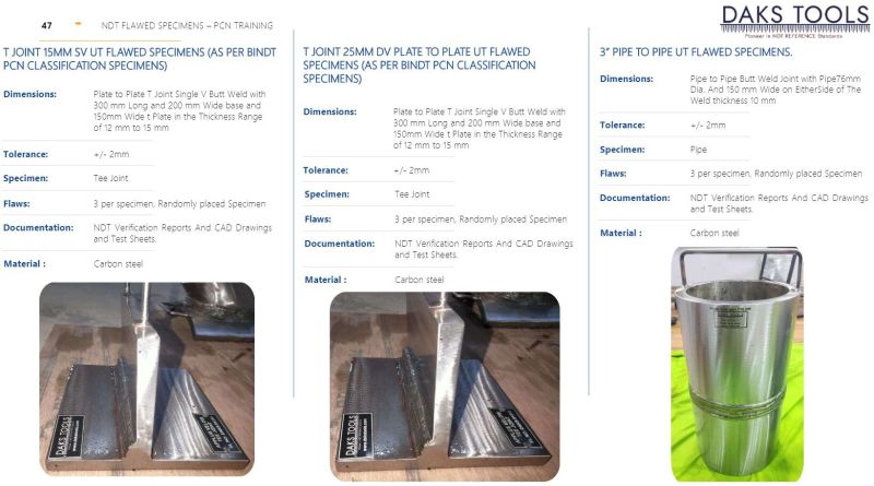
T JOINT 15MM SV UT FLAWED SPECIMENS (AS PER BINDT PCN CLASSIFICATION SPECIMENS)
Dimensions:Plate to Plate T Joint Single V Butt Weld with 300 mm Long and 200 mm Wide base and 150mm Wide t Plate in the Thickness Range of 12 mm to 15 mm.
Tolerance:+/- 2mm
Specimen:Tee Joint
Flaws:3 per specimen, Randomly placed Specimen
Documentation:NDT Verification Reports And CAD Drawings and Test Sheets.
Material:Carbon steel.

Vacuum Box Testing of butt, fillet and lap weld
Vacuum box testing is a non-destructive examination (NDE/NDT) used for locating welding leaks. A vacuum box and a compressor create a high or low-pressure vacuum and a detergent solution is applied to the test area. The detergent bubbles help to identify the leaks within the created pressure envelope. The main objective of the Vacuum box testing technique is to locate leaks in welds due to through-thickness discontinuities. This is accomplished by applying a solution to a weld and creating a differential pressure across the weld causing the formation of bubbles as leakage gas passes through the solution. This testing is to be performed prior to any main vessel or tank testing following the completion of all welding. This article will briefly explain the leak testing procedure using the vacuum box method that can be used for all metals.
Required Equipment for Vacuum Box Testing
Vacuum box test method employs the following equipment for welding checks
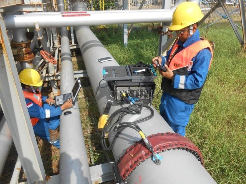
Long RangeUltrasonic testing(LRUT)Ultrasonic testing over a long distance is a quick approach to check for corrosion in pipelines. The approach can screen up to 100 metres of pipeline in a single test, 50 metres in each direction. Because of the high production coverage rates compared to manual techniques, LRUT has been used to screen piping systems above ground, but it is still the only reliable technique for screening pipe systems underground or underwater, where access is often limited or very costly for manual contact techniques. The technology is still improving, and the number of apps that use this system has grown significantly.A wave maker device drives low frequency (20-100 kHz) ultrasonic waves longitudinally through the pipeline wall by placing a ring of transducers around the pipeline. The approach succeroblems. At the same time, this allows for thessfully identifies changes in the cross-section of the pipeline, allowing it to detect corrosion and other puse of welds and flanges as distance markers.Long Range Ultrasonic Testing (LRUT) is a technique that involves placing an array of probes in a belt that is circumferentially wrapped around the pipe being inspected. The system then generates ultrasonic guided waves that travel longitudinally down the length of the pipe. The distance covered by the ultrasonic waves is determined by a variety of elements including pipe coating, branch connections, fittings, and whether the pipe is above ground or buried. As a result, the system can inspect both ways from each inspection location, maximising production.
Long-Range Ultrasonic Testing Benefits (LRUT)
")
IRIS is a non-destructive testing technology for pipes and tubes that uses ultrasonic waves.
Many plant operators in the oil and gas and power production industries face the issue of increasing asset efficiency and life expectancy while maintaining safety and reliability. As a result, proper inspection of critical components such as pipes and tubes is critical to maintaining the plant's integrity.
Internal Rotary Inspection System (IRIS) is a tube inspection system that can detect corrosion, pitting, and wall loss in boilers, heat exchangers, air coolers, and feed water heaters. IRIS is extremely versatile since it can be used on a wide range of tube diameters and wall thicknesses, and it is suited for both ferrous and non-ferrous materials.
n IRIS probe is inserted into a tube flooded with water. The probe is fitted with a transducer that generates an ultrasonic pulse along a path parallel to the axis of the tube. A rotating mirror directs the ultrasonic pulse into the tube wall. The mirror is driven by a small turbine that is rotated by the pressure of water pumped into the tube. The ultrasound pulses are reflected by the inner-diameter (ID) wall and outer-diameter (OD) wall of the tube and the time-of-flight difference between the two diameters is used to calculate the walls thickness. As the IRIS probe is pulled, the spinning motion of the mirror results in a helical scan path ensuring full coverage of the tube.
Merits of IRIS Tube Inspection
Sensitivity to both internal and external defects.
")
Phased array ultrasonic testing(PAUT) can be used for a multitude of tasks.
Today in the assessment of structures, flaws, fitness for use of the product or equipment, and assessment of critical parts require flaw data regarding location shape and size of the defect. PAUT can provide an accurate assessment of defect and material fracture analysis based on accepted standards.
PAUT is used to detect defects that cant be easily detected using conventional volumetric methods such as radiography and manual ultrasonic testing. Alpha Sonix specializes in providing PAUT support in petrochemical industries, oil, and gas, power, chemical industries. This method also finds applications in pressure vessels and structural welded components providing a high standard of quality assurance, when time-restricted inspections are necessary.
A PAUT probe is made up of multiple small ultrasonic probes which can be fired individually. By varying the time of the pulse of each probe ultrasonic rays can be steered into various angles and focal distances. Therefore, waves can be swept across the material and thereby covering the object.
Applications for PAUT:
Inspection of forging or casting materials
Weld inspection
Corrosion mapping
Scanning complex geometry
PAUT can detect:
Weld defects such as lack of fusion, slag inclusions, porosity, cracks, lack of penetration.
Erosion or corrosion.
Inherent discontinuities due to the manufacturing process used.
Environmentally damage.
PAUT has several advantages in comparison to other NDT. Information received can be displayed in a variety of formats like A, B, C scans for reliable and faster inspections. This data can be stored and reviewed later as the need arises. With the PAUT shutdown requirement is eliminated hence effect on the product is minimal.
ALPHA SONIXs PAUT inspectors are highly qualified, holding a minimum of ASNT (American Society of Non-destructive Testing) Level II. Our inspectors are highly qualified to inspect tubes such as condensers, AC tubes, heat exchangers that require special equipment and highly skilled inspectors. Alpha Sonix Inspector is more than capable of running such tasks while the highest level of consumer satisfaction.
")
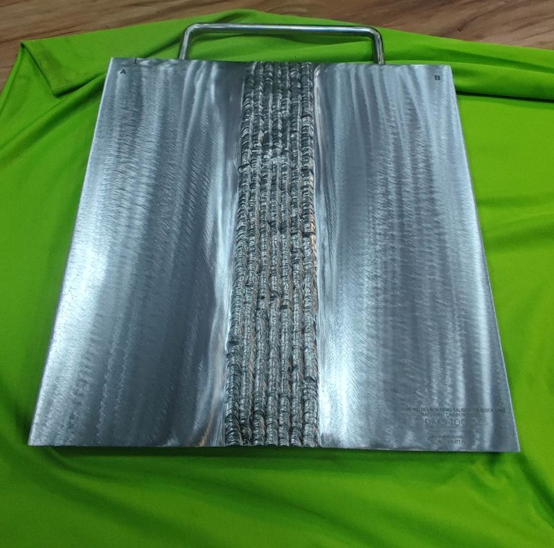
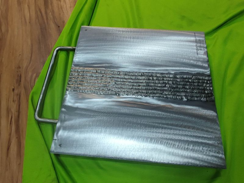
MAGNETIC FLUX LEAKAGE CALIBRATION TUBE (MFL).
Dimensions: Thickness based on customer requirements.
Description: Eddy current tube specifications. Are you prepared to request a standard quote? What we require is as follows: Which substance is it? (Wall, OD, and Alloy) The material will be supplied by the client or NDE? What size faults are required, and which ones? The majority of depths are indicated as a percentage of tube wall. Does the standard have to adhere to a specification? ASME, etc. Please send over any drawings or even just a quick hand sketch if you have any. We are experts in creating customised eddy current tubes and have years of experience cutting a wide variety of flaws. TWHs and FBHs, OD and ID grooves, milled flats, OD and ID thinning bands, ID FBHs, ID contoured flats, 120/180 wearscars, tapering faults, and more.
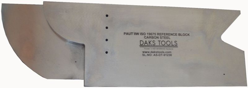
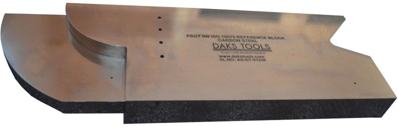
PAUT ISO 19675 CALIBRATION BLOCK
Dimensions:L X W X T (300mm X 100mm X 25mm).
Description:An international group of NDT professionals created thePAUT IIW Block in line with ISO 19675 with the specificgoal of developing a widely recognized, standardizedblock for Phased Array Ultrasonic Testing Calibrations.There were no international standards outlining aparticular block for calibrating PAUT systems prior to thecreation of this specification.
Geometry:25 x 100 x 300 mm (1" Thick x 4" Width x 12" Length), with radii of 4" (100mm) and 2" (50mm).
Material :Carbon Steel, Stainless Steel, Titanium, Aluminum, Alloy Steel.

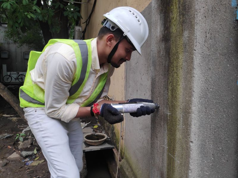
Rebound hammer testis conducted to find out the compressive strength of concrete by using rebound hammer. The rebound of an elastic mass depends upon the hardness of the surface when it strikes.
When the plunger ofrebound hammer testis pressed against the surface of the concrete, the mass rebounds and the extent of such a rebound depends upon the surface hardness of the concrete.
The spring-loaded hammer must travel with a consistent and reproducible velocity. The rebound distance of the steel hammer from the steel plunger is measured on a linear scale attached to the frame of the instrument.
The tests can be performed in horizontal, vertically upward, vertically downward or any intermediate angled positions in relation to the surface. The devices are furnished with correlation curves by the manufacturer.
ASTM C805 now states that these references to the relationship between the rebound hammer and compressive strength provided by the manufacturer shall be used only to provide indications of relative concrete strength at different locations in a structure.
To obtain greater accuracy of test results, it is recommended that the user develops a correlation for the device on each concrete mixture design to be tested and at the intended test angle.
Procedure to extract the appropriate result:
Prior to the test, therebound hammershould be tested against the anvil to get reliable results for which the manufacturer of the rebound hammer.indicates the range of readings on the anvil, suitable for different types of rebound hammer.
On applying light pressure on the plunger, it will release it from the locked position and allow it to extend to the ready position for the test.
Press the plunger to the surface of the concrete, the instrument being used perpendicular to the test surface. Apply a gradual increase in pressure until the hammer impacts.
Take an average of about 15 readings.

Fitness for Service (FFS) is a best practise and industry standard used in the oil and gas and chemical process industries to determine the fitness of in-service equipment for continuing operation.Corrosive conditions and/or excessive temperatures are frequently encountered by a process, facility, or equipment. The material used in the equipment can decay or age over time in these settings. When critical equipment, such as pressure vessels, pipes, and storage tanks, reaches the end of its useful life, the plant operator must decide whether it can continue to run safely and reliably to avoid accidents to employees and the public, environmental damage, and unplanned shutdowns. The plant operator can use fitness for service assessment techniques to make informed judgments based on recognised engineering principles.
Provider fitness Assessment is a multidisciplinary engineering examination that assures that all process and plant equipment, such as pressure vessels, pipes, and tanks, perform safely and reliably throughout the duration of the operation and until the next turnaround or planned downtime. ASME, API, BS 5500, and other internationally recognised design codes give rules/guidelines for determining suitability for service. This technique assesses the equipment's residual strength in its current state, which may have deteriorated from its initial state. Corrosion, localised corrosion, pitting and crevice corrosion, hydrogen attack, embrittlement, fatigue, high-temperature creep, and mechanical deformation are all common degradation mechanisms.
Fitness-for-service evaluations look at the structural integrity of components as well as their appropriateness for long-term use. The integrity of critical pressure components and welded structures can be tested against multiple failure modes utilising established engineering procedures such as BS 7910:2013, API 579/ASME FFS-1, ASME B31G, DNV-OS-F101, and FITNET.

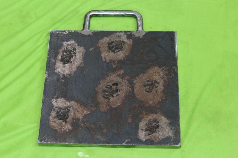
Corrosion, Erosion, UT Thickness Training & Certification Plates. Corrosion/Erosion and Pitting Specimens Plate Dimensions: Length 300mm X Width 200mm Thickness 15mm Carbon Steel Corrosion/Erosion Defects Were Placed Randomly On The Specimens. Some Of Specimens Will Have Naturally Obtained Corrosions/Erosions Recorded Depth Of The Corrosion Indications Will Be Based On The Deepest Spot Within The Field Of Corrosion. The Host Side Of The Plate Will Be Covered With A Removable Cover Plate.

The oil and gas, as well as the petrochemical industries, are under constant pressure to decrease risks and enhance safety and environmental challenges. Owners continue to make ongoing efforts to minimise production costs and improve maintenance procedures.In the hydrocarbon and chemical process sectors, as well as offshore pressure systems, the ALPHA SONIX team has extensive expertise designing risk-based inspection (RBI) procedures on fixed equipment and pipelines. These programmes are based on API RP 580, API RP 581, DNV-RP-G101, and best engineering practises and client specifications, as well as API RP 580, API RP 581, and DNV-RP-G101. Software and technology implementation are used to supplement the programmes.
WHAT IS RISK-BASED INSPECTION (RBI) AND HOW DOES IT WORK?Risk-Based Inspection (RBI) is an analysis methodology and process that, unlike condition-based inspection, necessitates a qualitative or quantitative assessment of the probability of failure (PoF) and consequence of failure (CoF) associated with each equipment item in a process unit, including piping circuits. Individual pieces of equipment are categorised by their hazards in a fully implemented RBI programme, and inspection activities are prioritised according on this category. A proper inspection and maintenance programme is then designed based on an estimate of the possibility and implications of failure associated with each piece of equipment, component, or structure.
WHAT IS THE IMPORTANCE OF RISK-BASED INSPECTION AND MAINTENANCE?RBI is used to detect and comprehend risk, risk drivers, and the lifecycle of equipment. RBI can determine whether an inspection is required; however, this requires additional data that is highly targeted in order to reduce the underlying uncertainties connected with the hazards associated with the equipment's existing and expected damage status. When an inspection will not improve knowledge of the damage situation, RBI should not be used to recommend it. RBI should highlight to alternate risk mitigation measures such as replacement, repair, or other activities that satisfy the risk criteria in those circumstances where PoF is driving the risk.
RBI is critical for maximising the efficiency of industrial plants in a variety of industries. It enables you to meet the industry's financial, dependability, and regulatory requirements by enhancing the performance, availability, and safety of your facility. It establishes a long-term testing and inspection programme, which extends the life of your plant.

Magnetic Particle Inspection (MPI) is an NDT method that can use magnetism to detect surface and subsurface discontinuities in ferromagnetic materials.
MPI is generally used to determine parts fitness for use. It is a relatively easy and quick method that is widely used in various sectors such as automotive, oil and gas, aerospace, petroleum, power generation, etc.
This method detects surface or subsurface discontinuities such as cracks, porosity, laps, seams, inclusions in ferromagnetic materials. One of the major advantages of this method is, it is a relatively fast method and gives an immediate indication on the surface.
This method works by inducing the magnetic flux in the part to be tested. If any discontinuities or detect is present on the surface or near the surface the magnetic field distorts and leaks around the defect. By application of magnetic medium on the surface, the particles attract the area where flux leakage has occurred producing a visible indication of the defect. This indication can be evaluated by the operator any necessary measures are taken if any.
Our techniques for magnetic particle inspection include:
Yoke
Bench (for headshot direct induction)
Coil shot
Prods
Central conductor
ALPHA SONIX has skilled NDT personnel that have gained years of experience in performing MPI and areLevel 2 and 3 qualified withASNT. We provide the testing both on-site at our customers premises.
When selecting ALPHA SONIX for your magnetic particle inspection (MPI) needs, you have an assurance that your maintenance schedules will be met and you will benefit from the expertise that our inspectors provide. Our reports will provide you with the necessary data to take preventive measures and will help in the management of assets.

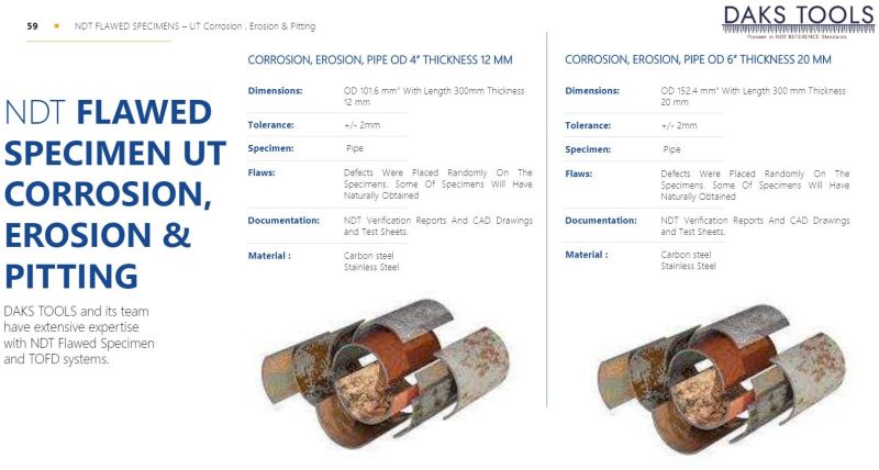
Corrosion, Erosion, Pipe OD 6 inch Thickness 20 mm Carbon Steel.
Dimensions:OD 6 With Length 300mm Thickness 20mm.Tolerance:+/- 2mmSpecimen:PipeFlaws:Defects Were Placed Randomly On The Specimens. Some Of Specimens Will Have Naturally Obtained.Documentation:NDT Verification Reports And CAD Drawings and Test Sheets.Material :Carbon steelStainless Steel


Corrosion, Erosion, Pipe OD 6 inch Thickness 20 mm Carbon Steel.
Dimensions:OD 4 With Length 300mm Thickness 12mm.Tolerance:+/- 2mmSpecimen:PipeFlaws:Defects Were Placed Randomly On The Specimens. Some Of Specimens Will Have Naturally Obtained.Documentation:NDT Verification Reports And CAD Drawings and Test Sheets.Material :Carbon steelStainless Steel

Being a prominent firm in this domain, we are engaged in offeringRadiography Testing Services.Offered service is performed under the strict supervision of our experts using optimum grade tools and latest technology. Our professionals perform this service as per the requirements of our clients. Moreover, this service can be availed by our clients at most reasonable price.
")

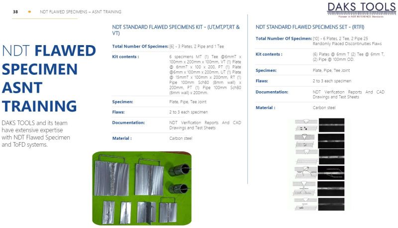
DAKS TOOLS NDT Standard Flawed Specimens Set - (RTFI)
Total Number Of Specimen:[10] - 6 Plates, 2 Tee, 2 Pipe 25Randomly Placed Discontinuities Flaws.
Kit contents :(6) Plates @ 6mm T (2) Tee @ 6mm T, (2) Pipe @ 100mm OD.
Specimen:Plate, Pipe, Tee Joint.
Flaws:2 to 3 each specimen.
Documentation:NDT Verification Reports And CADDrawings and Test Sheets.
")
T JOINT 6MM PLATE TO PLATE MT FLAWED SPECIMENS (AS PER BINDT PCN CLASSIFICATION SPECIMENS)
Dimensions:Plate to Plate T Joint With 6mm Thick plate, 250mm Long & 150mm base and 100mm Wide T.
Tolerance:+/- 2mm
Specimen:Pipe
Flaws:3 per specimen, Randomly placed Including One parent metal flaw.
Documentation:NDT Verification Reports And CAD Drawings and Test Sheets.
Material:Carbon steel.
TUBULAR NODES 12MM 45 UT FLAWED SPECIMENS (AS PER BINDT PCN CLASSIFICATION SPECIMENS)
Dimensions:Tubular Nodes Dihedral Angle 45 Main Pipe Segment 20 Dia. 20 to 25 mm WT & Branch152 Dia. And 10 mmTolerance:+/- 2mmSpecimen:Tubular Nodes
Flaws:3 per specimen, Randomly placed Specimen
Documentation:NDT Verification Reports And CAD Drawings and Test Sheets.
Material:Carbon steel.
")
TUBULAR NODES 15MM 40 UT FLAWED SPECIMENS (AS PER BINDT PCN CLASSIFICATION SPECIMENS)
Dimensions:Tubular Nodes Dihedral Angle 40 Main Pipe Segment 500mm Dia. 20 to 25 mm WT & Branch 200 Dia. And 12 mm.
Tolerance:+/- 2mm
Specimen:Tubular Nodes
Flaws:3 per specimen, Randomly placed Specimen
Documentation:NDT Verification Reports And CAD Drawings and Test Sheets.
Material:Carbon steel.
")
NDT STANDARD FLAWED SPECIMENS KIT ( MAGNETIC PARTICLE )
Total Number Of Specimen:[10] - 6 Plates, 2 Tee, 2 Pipe, 25 Random Placed Discontinuities Flaws.
Kit contents :(6) Plates @ 6mm T, (2) Tee @ 6mm T(2) Pipe @ 100mm OD.
Specimen:Plate, Pipe, Tee Joint
Flaws:2 to 3 each specimen
Documentation:Document Includes CAD Drawings, TestSheets & Radiographs Film Set.
Material :Carbon steel.
")
NDT STANDARD FLAWED SPECIMENS SET (RTFI)
Total Number Of Specimen:[10] 7 Plates, 1 Tee, 2 Pipe.
Kit contents :(4) Plates @ 9mm T, (3) Plates @ 15mmT, (1) Tee @ 9mm T, (2) Pipe @ 100mmSch80 (8mm wall)(2) Pipe @ 100mm OD.
Specimen:Plate, Pipe, Tee Joint.
Flaws:2 to 3 each specimen.
Documentation:Document Includes CAD Drawings, TestSheets & Radiographs Film Set.
Material :Carbon steel.
")
NDT STANDARD FLAWED SPECIMENS KIT (LIQUID PENETRANT)
Total Number Of Specimen:[10] - 6 Plates, 2 Tee, 2 Pipe, 25Randomly Placed Discontinuities Flaws.
Kit contents :(6) Plates @ 6mm T, (2) Tee @ 6mm T(2) Pipe @ 100mm OD
Specimen:Plate, Pipe, Tee Joint
Flaws:2 to 3 each specimen
Documentation:NDT Verification Reports And CADDrawings and Test Sheets
Material :Carbon steel
.")
NDT STANDARD FLAWED SPECIMENS KIT (RADIOGRAPHIC TESTING)
Total Number Of Specimen:[10] 8 Plates, 1 Tee, 1Pipe. 25 RandomlyPlaced Discontinuities Flaws. .
Kit contents :(5) Plates @ 9mm T (3) Plates @ 15mmT (1) Tee @ 9mm T (1) Pipe @ 100mmSch80 (8mm wall).
Specimen:Plate, Pipe, Tee Joint.
Flaws:2 to 3 each specimen.
Documentation:NDT Verification Reports And CADDrawings and Test Sheets.
Material :Carbon steel.
")
NDT STANDARD FLAWED SPECIMENS KIT ( EDDY CURRENT TESTING)
Total Number Of Specimen:[5] - 1 Plates, 1 Tee, 1 Pipe 1 CruciformType Joint, 1 Semi Cruciform Type Joint25 Randomly Placed DiscontinuitiesFlaws.
Specimen:Plate, Pipe, Tee Joint.
Flaws:2 to 3 each specimen.
Documentation:NDT Verification Reports And CADDrawings and Test Sheets.
Material :Carbon steel.
")
NDT STANDARD FLAWED SPECIMENS KIT (VISUAL TESTING)
Total Number Of Specimen:[10] - 6 Plates, 2 Tee, 2 Pipe 25Randomly Placed Discontinuities Flaws
Kit contents :(6) Plates @ 6mm T, (2) Tee @ 6mm T, (2) Pipe @100mm OD.
Specimen:Plate, Pipe, Tee Joint.
Flaws:2 to 3 each specimen.
Documentation:NDT Verification Reports And CADDrawings and Test Sheets.
Material :Carbon steel.
25MM SV PLATE TO PLATE UT FLAWED SPECIMENS
Dimensions:Plate to Plate Single V Butt Weld 300mm Long and 150mm Wide on Either Side of The Weld thickness 25mm.
Tolerance:+/- 2mm
Specimen:Plate
Flaws:3 per specimen, Randomly placed Specimen
Documentation:NDT Verification Reports And CAD Drawings and Test Sheets.
Material:Carbon steel
4 PIPE TO PIPE MT FLAWED SPECIMENS (AS PER BINDT PCN CLASSIFICATION SPECIMENS)
Dimensions:Pipe To Pipe Butt joint 100mm Dia. And 6 to 8mm WT with 100mm Long Pipe on either Side of the weld.
Tolerance:+/- 2mm
Specimen:Plate
Flaws:3 per specimen, Randomly placed Specimen
Documentation:NDT Verification Reports And CAD Drawings and Test Sheets RT Report.
Material:Carbon steel
6MM PLATE TO PLATE MT FLAWED SPECIMENS.
Dimensions:Plate to Plate Butt Joint with 6mm Thick plate, 250mm Long and 75mm Wide on Either Side of The Weld Including One parent metal flaw.
Tolerance:+/- 2mm
Specimen:Plate
Flaws:3 per specimen, Randomly placed Specimen
Documentation:NDT Verification Reports And CAD Drawings and Test Sheets.
Material:Carbon steel
PAUT AND TOFD PLATE DOUBLE V ASYMMETRICAL 1/3+2/3 THK FLAWED SPECIMENS
Dimensions:Plate to Plate Double V Butt Weld 400mm Long And 200mm Wide On Either Side Of The Weld Thickness Range > 20mm to 30mm ASYMMETRICAL 1/3+2/3 Thickness.
Tolerance:+/- 2mmSpecimen:PlateFlaws:3 per specimen, Randomly placed SpecimenDocumentation:NDT Verification Reports And CAD Drawings and Test Sheets.Material:Carbon steel

PAUT AND TOFD PLATE TO PLATE DOUBLE V FLAWED SPECIMENS
Dimensions:Plate to Plate Double V Butt Weld 500mm Long and 250 mm Wide on Either Side of The Weld Thickness Range >30 mm to 50mm.
Tolerance:+/- 2mm
Specimen:Plate
Flaws:3 per specimen, Randomly placed Specimen
Documentation:NDT Verification Reports And CAD Drawings and Test Sheets.
Material:Carbon steel
PAUT AND TOFD PLATE TO PLATE SINGLE V ASYMMETRICAL 1/3+2/3 THK FLAWED SPECIMENS
Dimensions:Plate to Plate Double V Butt Weld 500mm Long And 250 mm Wide On Either Side of the Weld Thickness range >30 mm to 50mm ASYMMETRICAL1/3+2/3 Thickness.
Tolerance:+/- 2mmSpecimen:PlateFlaws:3 per specimen, Randomly placed SpecimenDocumentation:NDT Verification Reports And CAD Drawings and Test Sheets.Material:Carbon steel
6MM PLATE TO PLATE PT FLAWED SPECIMENS
Dimensions:Plate to Plate Butt Joint with 6 mm Thick plate, 250 mm Long and 75 mm Wide on Either Side of The Weld Including One parent metal flaw.
Tolerance:+/- 2mm
Specimen:Plate
Flaws:3 per specimen, Randomly placed Specimen
Documentation:NDT Verification Reports And CAD Drawings and Test Sheets.
Material:Carbon steel

Near Field Array (NFA) tube testing is an electromagnetic testing method for detecting discontinuities on the internal surface of fin-fan type tubes and ferromagnetic (Carbon steel) heat exchanger tubes.
NFA Near field Array testing uses an array of coils (up to 30 coils) that activate in sequences, similar to ECA Eddy current array testing. Unlike traditional Eddy current testing, which only uses a bobbin coil, NFA Near field Array testing includes tangential coils that help gather detailed data and discontinuities in all directions.The most efficient test method for examining Aluminum finned carbon steel tubes is NFA Near field Array tube testing. Because the external aluminium fins interfere with the quality of the signals acquired, aluminium finned carbon steel tubes are the most difficult to check. Internal pitting, internal cracks at the tubesheet, internal erosion, and the resulting wall loss can all be detected with NFA Near field Array tube testing, which can also discriminate the location and size of discontinuities.For signal analysis and reporting,
This NFA method is:
Fast, Accurate, Traceable, and Archivablea digital paper trail
LMATS employs Eddyfi's Magnifi software. The software allows NFA Near field Array tube testing data to be shown and reported in 2D and 3D 'C' scan formats, which can help asset owners make informed decisions based on the accurate position and precision of the discontinuity.
Ideal Applications:
Advantages:

Near Field Testing (NFT) is a quick and low-cost approach for inspecting fin-fan carbon-steel tube. This method is based on a straightforward driver-pickup eddy current probe design that allows for quick signal analysis. Internal corrosion, erosion, and pitting in carbon steel tubing can all be detected with NFT. The NFT probes translate lift-off, also known as "fill factor, " into amplitude-based signals. The fin geometry on the outside of the tube has no effect on NFT probes since eddy-current penetration is limited to the tube's inner surface.
NFT Inspection's Benefits

EDDY CURRENT TESTING OF TUBES
ECT is an NDT method mostly used to examine tubing in heat exchangers tubes, generators, condensers, air coolers.
Eddy current testing (ECT) is an effective way of assessing conditions and fitness for use of pipes and tubes in petrochemical, aerospace, chemical, automobile, oil and gas, and various other industries. It is used for the detection of corrosion, cracks, coating thickness, and wear changes in the tube.
It is a fast inspection technique and a major advantage of the method is that there is minimal surface preparation. But this technique is only suitable for non-ferrous and conductive material such as copper, stainless steel, titanium, etc.
ECT (eddy current testing) uses the principle of electromagnetic induction to identify defects in the tubes. A probe is inserted along the length of the tube and pushed along its entire length. Eddy current is generated by the coil which Is present in the probe. Theses eddy currents and any disturbance in them are noted simultaneously on the screen by measuring electrical impedance. This impedance is noted on the screen and any defect that is present is identified.
A benefit of eddy current testing (ECT) is fast and real-time assessment can be done.
Eddy current testing of tubes is highly specialized, requiring expertise in special types of equipment. Alpha Sonixs non-destructive testing inspectors are ASNT Level II and III qualifiedin eddy current testing and have many years of valuable experience in the inspection of tubes. Our inspectors bring expertise which helps in the accurate assessment so you can make an informed decision based on the accurate data being measured.
Alpha Sonix IS committed to providing Total Quality Assurance and ensuring inspections meet deadlines, standards, and are carried out safely and efficiently. While the schedule of maintenance is coordinated in such a way that minimizes disruption in business occurs while providing an optimum level of inspection within minimum possible time.
")
6MM PLATE TO PLATE VT FLAWED SPECIMENS (AS PER BINDT PCN CLASSIFICATION SPECIMENS)
Dimensions:Plate to Plate Butt Joint with 6mm Thick plate, 250mm Long and 75mm Wide on Either Side of The Weld.
Tolerance:+/- 2mm
Specimen:Plate
Flaws:3 per specimen, Randomly placed Including One parent metal flaw.
Documentation:NDT Verification Reports And CAD Drawings and Test Sheets.
Material:Carbon steel
")


")

")


")


")

")